Related Manuals |
|
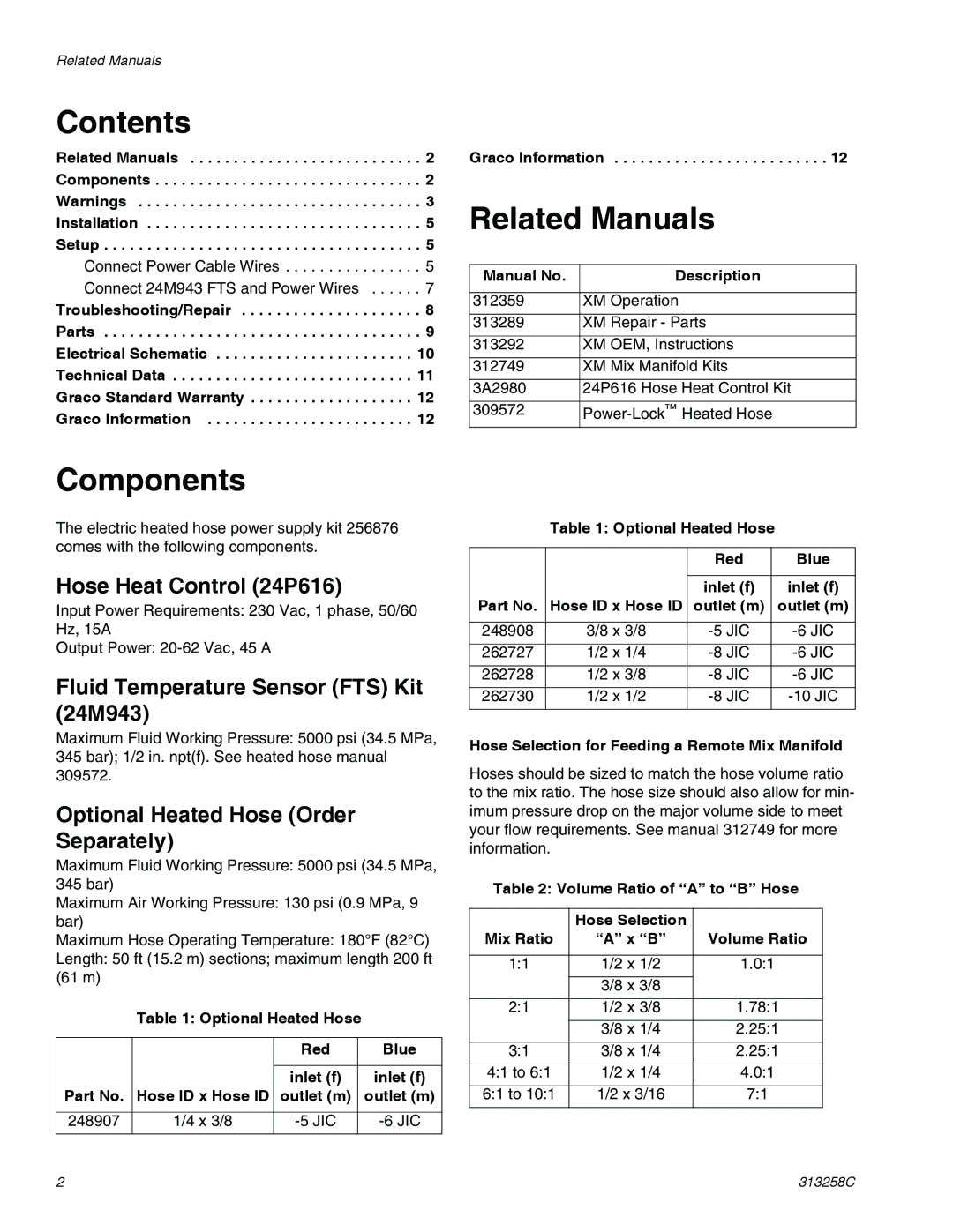
Contents |
|
Related Manuals | . 2 |
Components | . 2 |
Warnings | . 3 |
Installation | . 5 |
Setup | . 5 |
Connect Power Cable Wires | . 5 |
Connect 24M943 FTS and Power Wires | . 7 |
Troubleshooting/Repair | . 8 |
Parts | . 9 |
Electrical Schematic | 10 |
Technical Data | 11 |
Graco Standard Warranty | 12 |
Graco Information | 12 |
Graco Information . . . . . . . . . . . . . . . . . . . . . . . . . 12
Related Manuals
Manual No. | Description |
|
|
312359 | XM Operation |
|
|
313289 | XM Repair - Parts |
|
|
313292 | XM OEM, Instructions |
|
|
312749 | XM Mix Manifold Kits |
|
|
3A2980 | 24P616 Hose Heat Control Kit |
|
|
309572 |
Components
The electric heated hose power supply kit 256876 comes with the following components.
Hose Heat Control (24P616)
Input Power Requirements: 230 Vac, 1 phase, 50/60 Hz, 15A
Output Power:
Fluid Temperature Sensor (FTS) Kit (24M943)
Maximum Fluid Working Pressure: 5000 psi (34.5 MPa, 345 bar); 1/2 in. npt(f). See heated hose manual 309572.
Optional Heated Hose (Order Separately)
Maximum Fluid Working Pressure: 5000 psi (34.5 MPa, 345 bar)
Maximum Air Working Pressure: 130 psi (0.9 MPa, 9 bar)
Maximum Hose Operating Temperature: 180°F (82°C)
Length: 50 ft (15.2 m) sections; maximum length 200 ft (61 m)
Table 1: Optional Heated Hose
|
| Red | Blue |
|
|
|
|
|
| inlet (f) | inlet (f) |
Part No. | Hose ID x Hose ID | outlet (m) | outlet (m) |
|
|
|
|
248907 | 1/4 x 3/8 | ||
|
|
|
|
Table 1: Optional Heated Hose
|
| Red | Blue |
|
|
|
|
|
| inlet (f) | inlet (f) |
Part No. | Hose ID x Hose ID | outlet (m) | outlet (m) |
|
|
|
|
248908 | 3/8 x 3/8 | ||
|
|
|
|
262727 | 1/2 x 1/4 | ||
|
|
|
|
262728 | 1/2 x 3/8 | ||
|
|
|
|
262730 | 1/2 x 1/2 | ||
|
|
|
|
Hose Selection for Feeding a Remote Mix Manifold
Hoses should be sized to match the hose volume ratio to the mix ratio. The hose size should also allow for min- imum pressure drop on the major volume side to meet your flow requirements. See manual 312749 for more information.
Table 2: Volume Ratio of “A” to “B” Hose
| Hose Selection |
|
Mix Ratio | “A” x “B” | Volume Ratio |
|
|
|
1:1 | 1/2 x 1/2 | 1.0:1 |
|
|
|
| 3/8 x 3/8 |
|
|
|
|
2:1 | 1/2 x 3/8 | 1.78:1 |
|
|
|
| 3/8 x 1/4 | 2.25:1 |
|
|
|
3:1 | 3/8 x 1/4 | 2.25:1 |
|
|
|
4:1 to 6:1 | 1/2 x 1/4 | 4.0:1 |
|
|
|
6:1 to 10:1 | 1/2 x 3/16 | 7:1 |
|
|
|
2 | 313258C |