Manuals
/
Graco
/
Household Appliance
/
Heat Pump
Graco
425, 300
important safety instructions
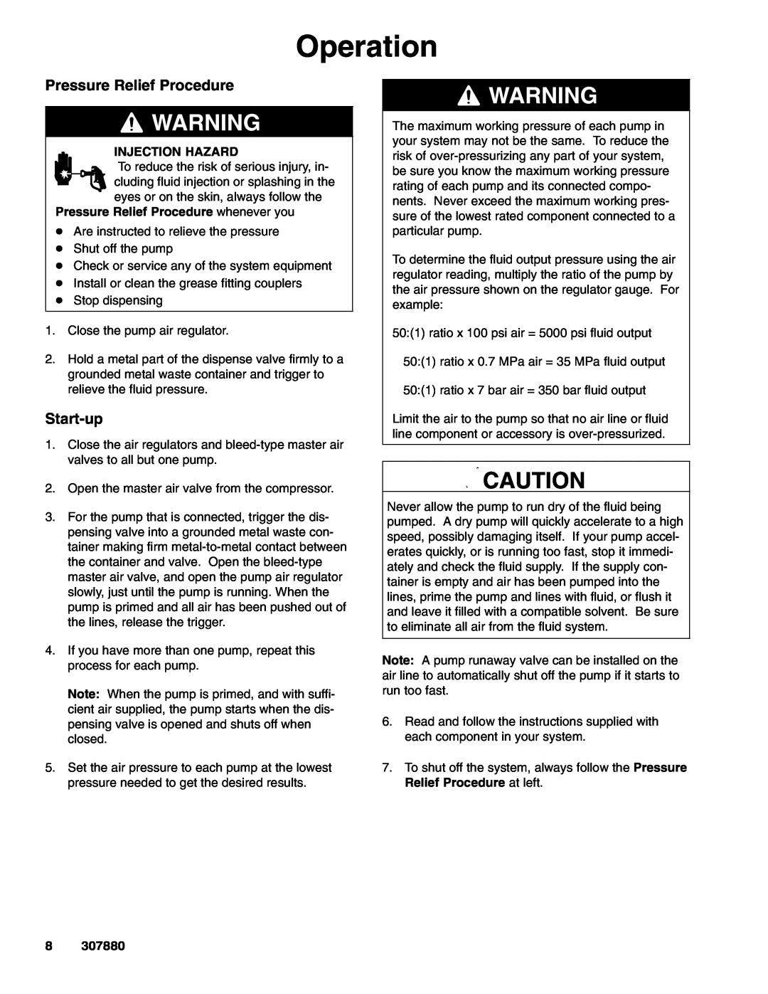
Operation, Pressure Relief Procedure, Start-up
Models:
300
425
1
8
16
16
Download
16 pages
29.73 Kb
5
6
7
8
9
10
11
12
Install
Parts list
Warranty
Air Line and Accessories
Pressure Relief Procedure
Page 8
Image 8
Page 7
Page 9
Page 8
Image 8
Page 7
Page 9
Contents
Instructions - Parts List
Fire-BallR 300 and
Grease Pumps
307880K
Table of Contents
Symbols
Warning Symbol
Caution Symbol
SKIN INJECTION HAZARD
MOVING PARTS HAZARD
FIRE AND EXPLOSION HAZARD
TOXIC FLUID HAZARD
Ground all of this equipment
Installation
Grounding
Typical Installation For Stationary Mountings
Installing the Hose Kit See Fig
Stationary Mounting Layout
Open Drum, Cover Mounted Pumps
Air Line and Accessories
Installation
Grounding
Fire-Ball300 pump shown
Typical Installation For Mobile Mountings
Mobile Mounting Layout
Drum With Hold-downKit
See Fig.Mounting
Start-up
Pressure Relief Procedure
Operation
307880
Parts Drawings and Lists
50 1 Fire-Ball300, 120-lbdrum size
75 1 Fire-Ball425, 120-lbdrum size
Description
50 1 Fire-Ball300, 400-lbdrum size
Parts Drawings and Lists
307880
Description
50 1 Fire-Ball425, 120-lbdrum size
Parts Drawings and Lists
50 1 Fire-Ball300, 120-lbdrum size
75 1 Fire-Ball425, 120-lbdrum size
75 1 Fire-Ball425, 400-lbdrum size
Parts Drawings and Lists
50 1 Fire-Ball300, 400-lbdrum size
307880
Model
Parts Drawings and Lists
Model
Description
50 1 and 75 1 Fire-Ball425 Pumps
Sound Data
50 1 Fire-Ball300 Pumps
Graco Standard Warranty
Graco Phone Numbers
FOR GRACO CANADA CUSTOMERS
Sales Offices Minneapolis
Top
Page
Image
Contents