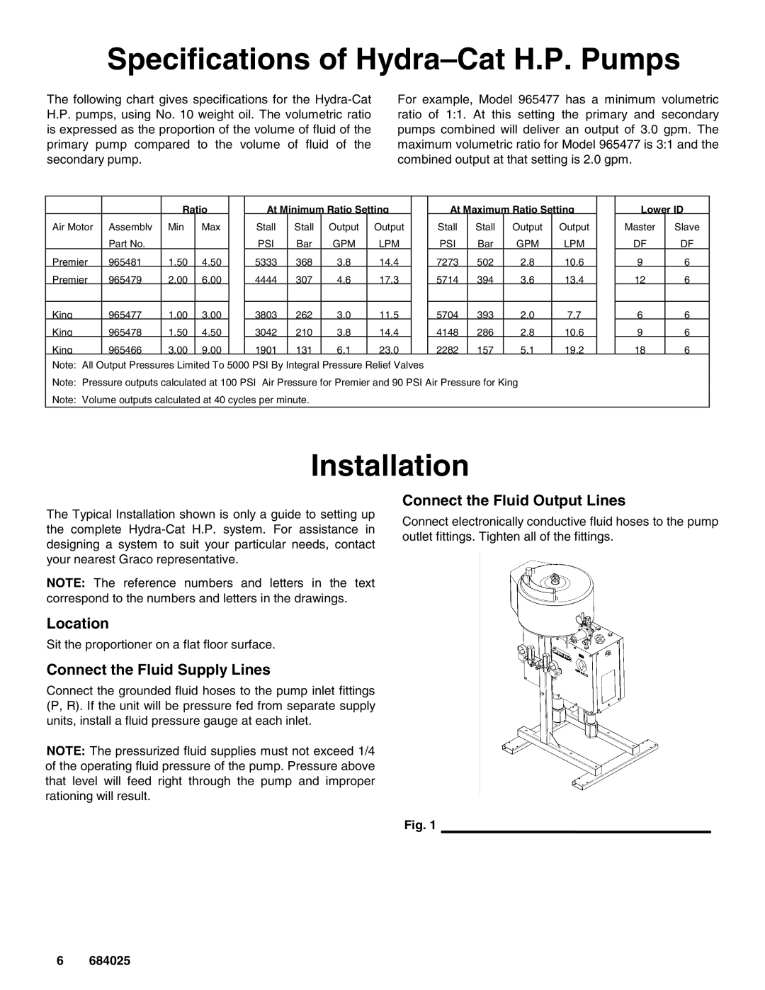
965466, 965479, 965481, 965478, 965477 specifications
The Graco 965466, 965477, 965481, 965478, and 965479 are part of Graco's robust line of paint sprayers, designed with durability, efficiency, and ease of use in mind. Each model features advanced technologies that cater to both professionals and DIY enthusiasts, ensuring a clean, even finish in a variety of painting applications.At the heart of these models is the Graco ProConnect system, which allows for quick and easy changes of the pump. This innovative feature minimizes downtime during projects, providing users with a seamless painting experience. The pumps are designed to handle a wide range of materials, from thin coatings to thicker paints, broadening their usability across diverse surfaces and project requirements.
One of the standout technologies in these models is the SmartControl system. This technology delivers a consistent spray fan throughout the pressure range, eliminating the frustrations of uneven paint application. The adjustable pressure control allows users to tailor the flow to their specific needs, leading to better coverage and fewer material waste.
These sprayers are equipped with a powerful electric motor, which ensures reliable operation on even the toughest jobs. The robust construction of each model guarantees longevity, making them a wise investment for those who frequently tackle painting tasks. Additionally, the lightweight design of these sprayers means they can be easily transported between job sites.
Another significant feature is the Graco FinishPro guard system, which helps maintain the integrity of the spray tip and provides improved spraying performance. This system extends the life of the tip while ensuring that the paint is delivered with precision and accuracy.
Each of the Graco models offers ergonomic designs, ensuring that users work comfortably over extended periods. Features such as padded grips and adjustable handles contribute to enhanced user experience, reducing fatigue during large projects.
Finally, all models come with Graco's standard two-year warranty. This provides peace of mind to users, knowing they are backed by a reputable manufacturer committed to quality and customer satisfaction.
In summary, the Graco 965466, 965477, 965481, 965478, and 965479 paint sprayers are engineered for superior performance, featuring innovations like the ProConnect system, SmartControl technology, and durable construction that meet the demands of varying painting tasks. Whether for professional contractors or enthusiastic DIYers, these sprayers offer the reliability and efficiency needed for a flawless finish.

