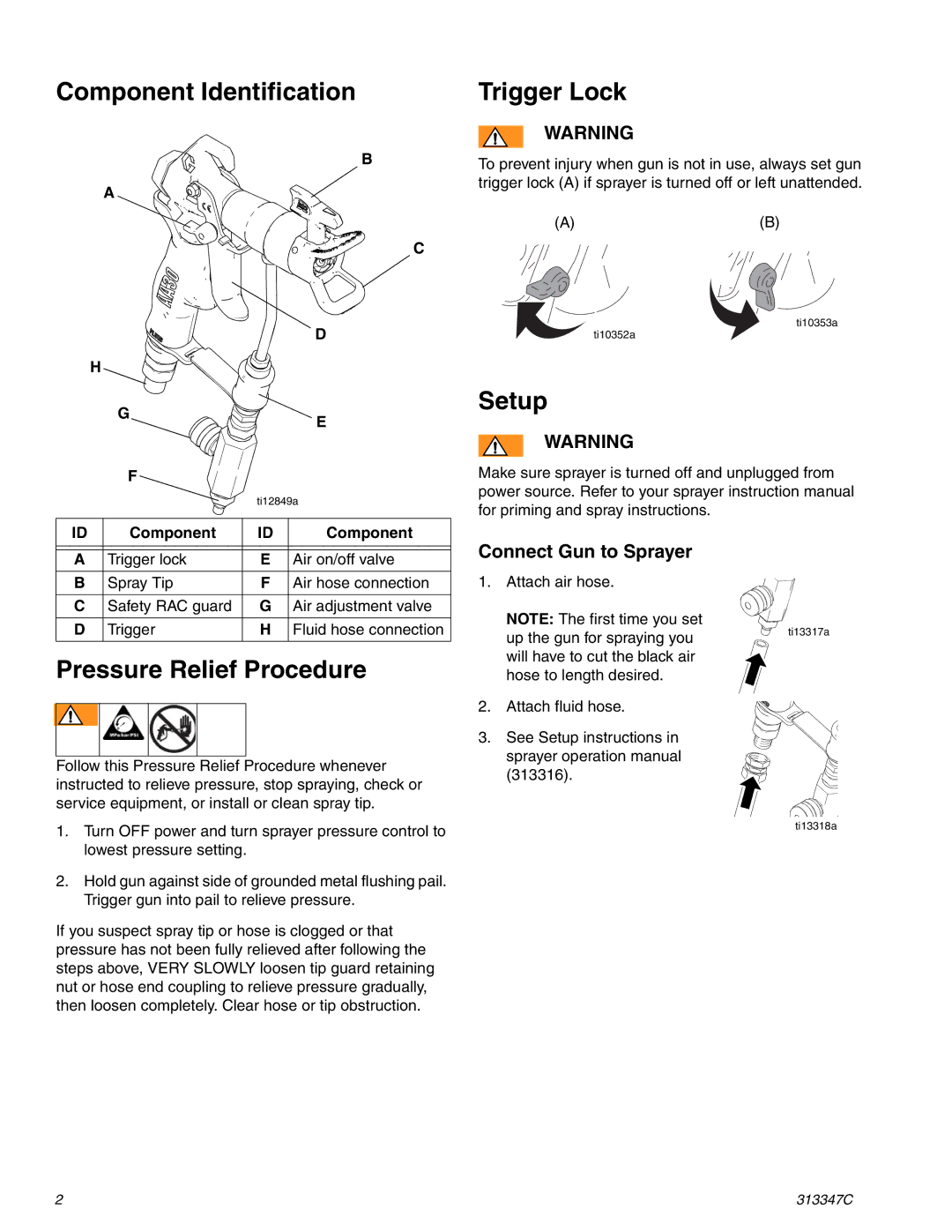
Component Identification
B
A
C
|
|
|
| D |
| H |
|
| |
|
| G |
| E |
|
|
|
| |
|
| F |
|
|
|
|
| ti12849a | |
|
|
|
|
|
ID |
| Component | ID | Component |
|
|
|
|
|
|
|
|
|
|
A |
| Trigger lock | E | Air on/off valve |
|
|
|
|
|
B |
| Spray Tip | F | Air hose connection |
|
|
|
|
|
C |
| Safety RAC guard | G | Air adjustment valve |
|
|
|
|
|
D |
| Trigger | H | Fluid hose connection |
|
|
|
|
|
Pressure Relief Procedure
Follow this Pressure Relief Procedure whenever instructed to relieve pressure, stop spraying, check or service equipment, or install or clean spray tip.
1.Turn OFF power and turn sprayer pressure control to lowest pressure setting.
2.Hold gun against side of grounded metal flushing pail. Trigger gun into pail to relieve pressure.
If you suspect spray tip or hose is clogged or that pressure has not been fully relieved after following the steps above, VERY SLOWLY loosen tip guard retaining nut or hose end coupling to relieve pressure gradually, then loosen completely. Clear hose or tip obstruction.
2
Trigger Lock
WARNING
To prevent injury when gun is not in use, always set gun trigger lock (A) if sprayer is turned off or left unattended.
(A) | (B) |
ti10353a
ti10352a
Setup
WARNING
Make sure sprayer is turned off and unplugged from power source. Refer to your sprayer instruction manual for priming and spray instructions.
Connect Gun to Sprayer
1. Attach air hose.
NOTE: The first time you set
up the gun for spraying you | ti13317a |
| |
will have to cut the black air |
|
hose to length desired. |
|
2. Attach fluid hose.
3. See Setup instructions in sprayer operation manual (313316).
ti13318a
313347C