Set-Up
Hose Attachment
1.Push in and rotate the trigger lock to stop the trigger from being activated.
2.Attach the (black p/n
3.Attach the (yellow p/n 236) solvent line to the solvent inlet fitting on the back of the gun.
4.Attach the (stainless steel p/n
5.Attach the (Clear) trigger air tubing to the trigger air inlet fitting on the back of the gun.
6.If the optional fiberglass roving chopper is being used, attach the “red” chopper air line to the chopper air inlet fitting on the back of the gun.
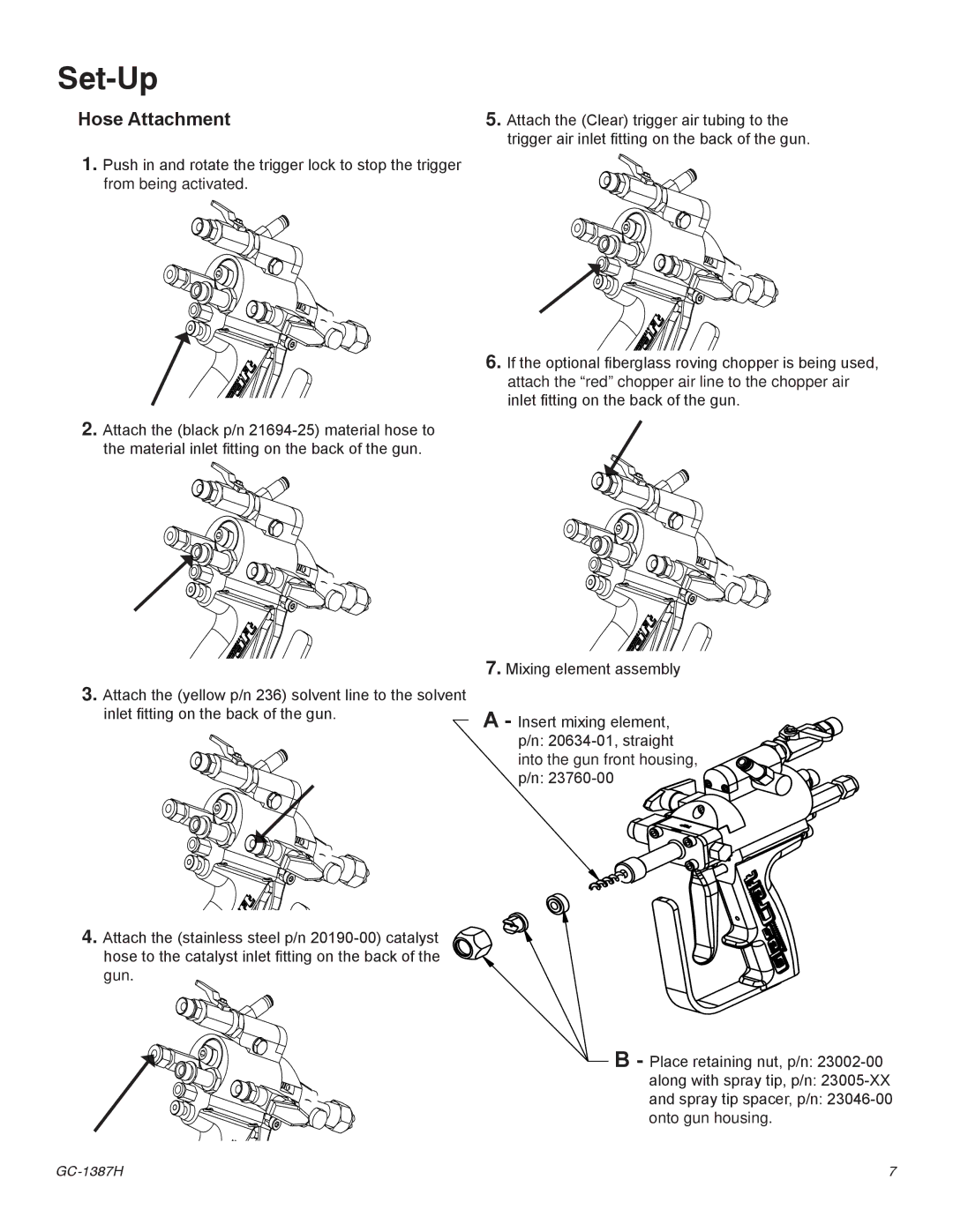
7.Mixing element assembly
A - Insert mixing element, p/n:
B- Place retaining nut, p/n:
7 |