How to Assembly

EnsamblajeAssemblee

Handle

Enclosed in carton are the; mower handle parts (2 upper handlebar pieces and 2 lower pieces) and hardware package (for contents, see back cover).

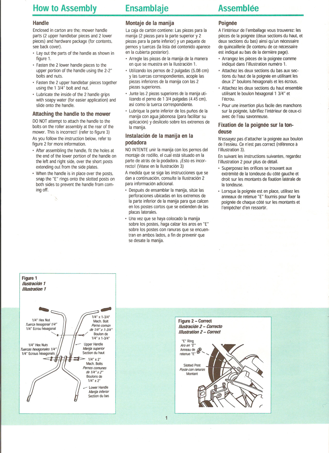
Layout the parts of the handle as shown in figure 1.

Fasten the 2 lower handle pieces to the

upper portion of the handle using the 2-2" bolts and nuts.

Fasten the 2 upper handlebar pieces together using the 1 3/4" bolt and nut.

Lubricate the inside of the 2 handle grips

with soapy water (for easier application) and slide onto the handle.

Attaching the handle to the mower

DO NOT attempt to attach the handle to the bolts on the roller assembly at the rear of the mower. This is incorrect! (refer to figure 3) As you follow the instruction below, refer to figure 2 for more information.

After assembling the handle, fit the holes at the end of the lower portion of the handle on the left and right side, over the short posts extending out from the side plates.

When the handle is in place over the posts, snap the "E" rings onto the slotted posts on both sides to prevent the handle from com- ing off.

Montaje de la manUa

La caja de carton contiene: Las piezas para la manUa (2 piezas para la parte superior y 2 piezas para la parte inferior) y un paquete de pernos y tuercas (la lista del contenido aparece en la cubierta posterior).

Arregle las piezas de la manUa de la manera en que se muestra en la Ilustracion 1.

Utilizando los pernos de 2 pulgadas (5.08 em) y las tuercas correspondientes, acople las piezas inferiores de la manUa con las 2 piezas superiores.

Junte las 2 piezas superiores de la manUauti- lizando el perno de 1 3/4 pulgadas (4.45 em), asi corno la tuerca correspondiente.

Lubrique la parte inferior de los PUr10S de la manUa con aguajabonosa (para facilitar su aplicaci6n) y deslfcelo sobre los extrernos de la rnanUa.

Instalaci6n de la manUa en la

podadora

NO INTENTE unir la rnanUa con los pernos del rnontaje de rodillo, el cual esta situado en la parte de atras de la podadora. iEsto es incor- recto! (Vease en la lIustracion 3)

A medida que se siga las instrucciones que se dan a continuacion, consulte la Ilustracion 2

para informacion adicional.

Despues de ensamblar la manUa, sitiJe las perforaciones ubicadas en los extremos de la parte inferior de la manUa para que calcen en los postes cortos que se extienden de las placas laterales.

Una vez que se haya colocado la manUa sobre los postes, haga calzar los aros en "E" sobre los postes con ranuras que se encuen- tran en ambos lados, a fin de prevenir que se desate la manUa.

Poignee

A I'interieur de I'emballagevous trouverez: les pieces de la poignee (deux sections du hauL et deux sections du bas) ainsi qu'un necessaire de quincaillerie (Ie contenu de ce necessaire est indique au bas de la derniere page).

Arrangez les pieces de la poignee comme indique dans I'illustration numero 1.

Attachez les deux sections du bas aux sec- tions du haut de la poignee en utilisant les deux 2" boulons hexagonals et les ecrous.

Attachez les deux sections du haut ensemble

utilisant Ie boulon hexagonal 1 3/4" et I'ecrou.

Pour une insertion plus facile des manchons

sur la poignee, lubrifiez I'interieur de ceux-ci avec de I'eausavonneuse.

Fixation de la poignee sur la ton- deuse

N'essayezpas d'attacher la poignee aux boulon de I'essieu.Ce n'estpas correct (reference a I'illustration 3).

En suivant les instructions suivantes, regardez I'illustration 2 pour plus de detail.

Superposez les orifices se trouvant aux

extremite de la tondeuse du cote gauche et droit sur les montants de fixation laterale de

la tondeuse.

Lorsque la poignee est en place, utilisez les anneaux de retenue "E" fournis pour fixer la poignee de chaque cote sur les montants et I'empecherd'enressortir.

Figure 1

IIustracion 1

Illustration 1

1/4" Hex Nut

Tuerca hexagonal 7/4" 1/4" Ecmu hexagonal

""'-e

1/4" Hex Nuts

Tuercas hexagona/es .7/4" 1/4" Ecrous hexagonals I.

~

1/4" x 1-3/4"

Mach. Bolt

Perno comtJn

de 7/4" x 7-3/4"

/Boulon de

1/4" x 1-3/4"

Upper Handle

Manfja superior

Section du haut

Figure 2 - Correct

IIustracion 2 - Correcto

Illustration 2 - Correct

___ Lower Handle

Manfja inferior Section du bas

Page 2
Image 2
Great States 204-14, 404-14, 303-145, 304-14 owner manual How to Assembly EnsamblajeAssemblee

404-14, 303-145, 304-14, 204-14 specifications

Great States 304-14, 404-14, 204-14, and 303-145 represent a collection of advanced turf management equipment designed primarily for precise lawn care and landscaping solutions. These models, produced by Great States, are known for their reliability, efficiency, and innovative features tailored to meet the demands of both homeowners and professional landscapers.

The Great States 304-14, a push reel mower, is ideal for residential lawns. Its key feature is the 14-inch cutting width combined with a lightweight design, making it easy to maneuver even in tight spaces. The 304-14 utilizes a 5-blade reel that guarantees a clean and precise cut, promoting healthier grass growth. Its adjustable cutting height allows users to customize the trim according to their lawn's needs.

Next, the Great States 404-14 also boasts a 14-inch cutting width but is equipped with added features such as a cushioned handle for better grip and comfort. This model's robust construction ensures durability, while its quiet operation is a significant advantage for users in residential neighborhoods. The 404-14 is perfect for users who seek an eco-friendly option, as the absence of fuel and emissions makes it a sustainable choice.

The Great States 204-14 is another versatile option in the lineup. It is noted for its high efficiency and design, which caters to users looking for a combination of functionality and ease of use. This model includes a larger rear wheel, providing improved traction on uneven terrains. The 204-14’s innovative cutting system allows it to handle both thick grass and light brush, making it suitable for varied lawn conditions.

Lastly, the Great States 303-145 takes the experience to the next level with its larger 21-inch cutting width. This self-propelled model features a powerful engine that enhances its performance on larger properties. The adjustable speed settings allow users to optimize their mowing experience based on the task. Additionally, the 303-145 supports a mulching option, allowing grass clippings to be finely shredded and returned to the soil, providing nutrients and reducing waste.

In summary, the Great States 304-14, 404-14, 204-14, and 303-145 are a testament to quality turf management. With features designed for ease of use, comfort, and environmental consideration, these models cater to diverse landscaping needs while providing exceptional performance and reliability in maintaining beautiful lawns. Whether for small gardens or expansive properties, Great States equipment stands out in the turf care industry.