Attach the Grille | Fig. 8 |
1. If lighted grille is being used, plug wire into fan socket.
If lighted grille and ceiling radiation damper are being used, plug wire from lighted grille into ceiling radiation damper socket. Do not plug wire directly into the fan socket. Make sure the wire does not interfere with the ceiling radiation damper operation.
2. Attach grille with two screws provided. Make sure not to over tighten; over tightening will damage grille.
3. Slide attachment screw covers over the attachment screws, shown in Figure 8 and 9.
4.If lighted grille is being used, install light bulb(s) into light socket(s). For incandescent lights, use maximum 100 watt bulb (by others). For fluorescent lights, use 27W GU24 bulbs. Greenheck has replacement 27W GU24 bulbs call
5.If lighted grille is being used, snap lens into place, by pushing on the outside edges of lens, shown in Fig. 9. To remove lens, use small screw driver and pry on one side of lens.
6.Turn on power and check fan and light operation.
Fig. 9
Squeeze ![]() tabs to insert/remove lens
tabs to insert/remove lens
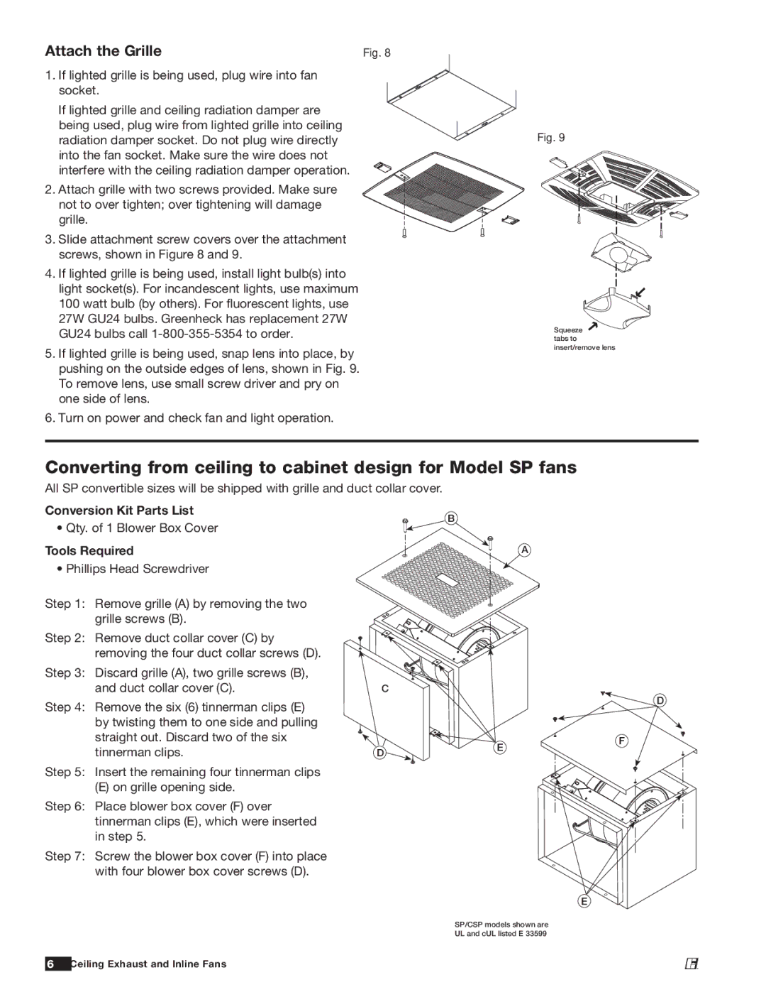
Converting from ceiling to cabinet design for Model SP fans
All SP convertible sizes will be shipped with grille and duct collar cover.
Conversion Kit Parts List
B
• Qty. of 1 Blower Box Cover
Tools Required | A |
• Phillips Head Screwdriver
Step 1: Remove grille (A) by removing the two grille screws (B).
Step 2: Remove duct collar cover (C) by removing the four duct collar screws (D).
Step 3: | Discard grille (A), two grille screws (B), |
|
| and duct collar cover (C). | C |
Step 4: | Remove the six (6) tinnerman clips (E) |
|
| by twisting them to one side and pulling |
|
| straight out. Discard two of the six |
|
![]() D
D
tinnerman clips. | D |
Step 5: Insert the remaining four tinnerman clips |
|
(E) on grille opening side. |
|
Step 6: Place blower box cover (F) over tinnerman clips (E), which were inserted in step 5.
Step 7: Screw the blower box cover (F) into place with four blower box cover screws (D).
E
F
E
SP/CSP models shown are
UL and cUL listed E 33599
6 Ceiling Exhaust and Inline Fans
®