Typical Installations
Models G and GB
Fan Inlet Connections
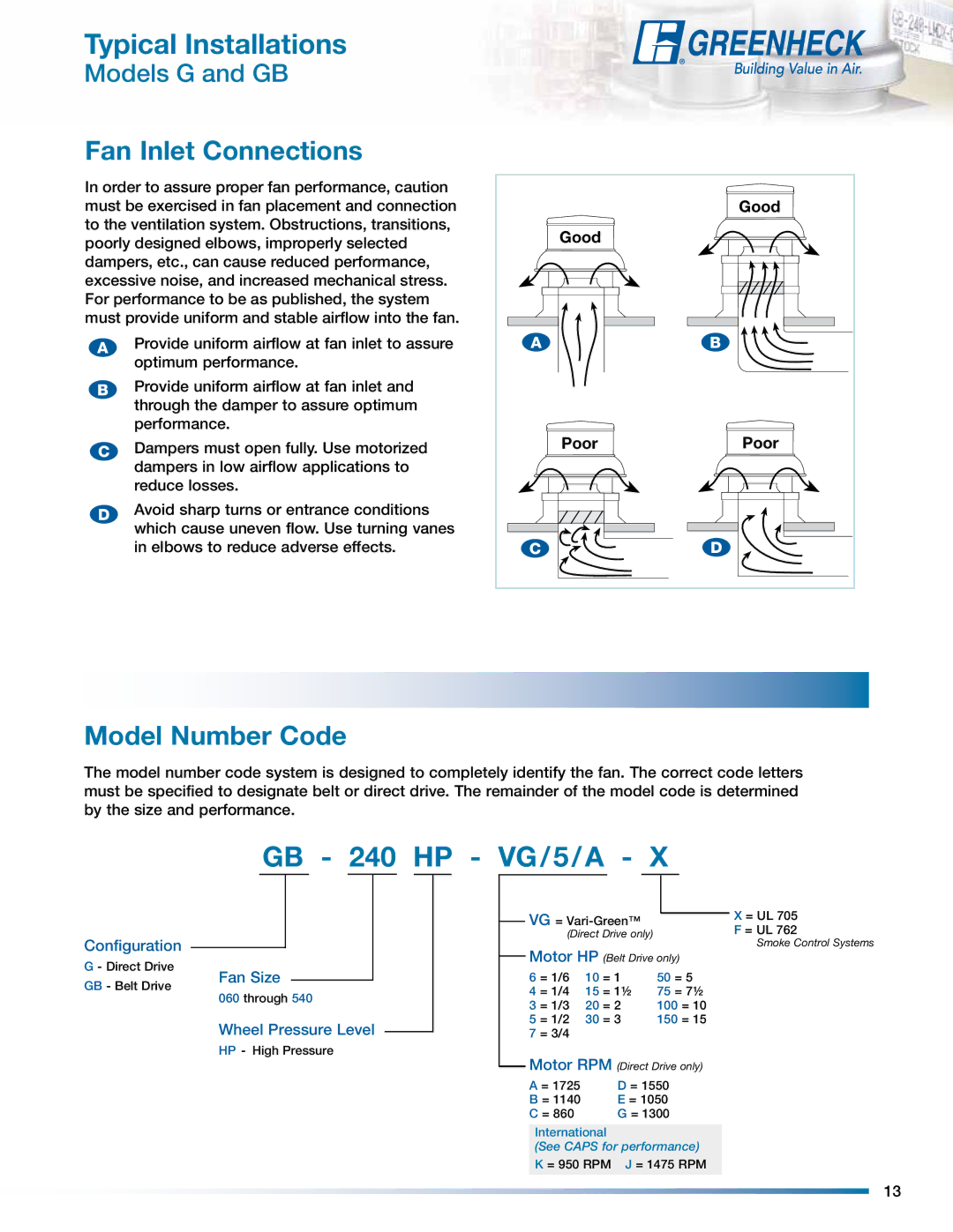
In order to assure proper fan performance, caution must be exercised in fan placement and connection to the ventilation system.. Obstructions, transitions, poorly designed elbows, improperly selected dampers, etc.., can cause reduced performance, excessive noise, and increased mechanical stress.. For performance to be as published, the system must provide uniform and stable airflow into the fan.
AProvide uniform airflow at fan inlet to assure optimum performance..
BProvide uniform airflow at fan inlet and through the damper to assure optimum performance..
CDampers must open fully. Use motorized dampers in low airflow applications to reduce losses..
DAvoid sharp turns or entrance conditions which cause uneven flow. Use turning vanes in elbows to reduce adverse effects.
| Good |
Good |
|
A | B |
Poor | Poor |
C | D |
Model Number Code
The model number code system is designed to completely identify the fan.. The correct code letters must be specified to designate belt or direct drive.. The remainder of the model code is determined by the size and performance.
GB - 240 HP - VG/5/A - X
Configuration |
|
|
|
|
|
|
|
|
|
|
|
|
|
|
|
|
|
|
|
|
|
| |
G - Direct Drive | Fan Size |
|
|
|
|
|
|
|
| ||
GB - Belt Drive |
|
|
|
|
|
|
|
| |||
|
|
|
|
|
|
|
| ||||
060 through 540 |
|
|
| ||||||||
|
|
|
| ||||||||
| Wheel Pressure Level |
|
|
|
| ||||||
|
|
|
|
| |||||||
| HP - High Pressure |
|
|
| |||||||
VG = |
|
|
|
|
| X = UL 705 | ||
|
|
|
| |||||
(Direct Drive only) |
|
|
|
| F = UL 762 | |||
|
|
|
|
|
|
|
| Smoke Control Systems |
Motor HP (Belt Drive only) | ||||||||
6 = 1/6 | 10 | = 1 |
| 50 | = 5 |
| ||
4 = 1/4 | 15 | = 11/2 |
| 75 | = 71/2 |
| ||
3 = 1/3 | 20 | = 2 |
| 100 = 10 |
| |||
5 = 1/2 | 30 | = 3 |
| 150 = 15 |
| |||
7 = 3/4 |
|
|
|
|
|
|
|
|
Motor RPM (Direct Drive only)
A = 1725 | D = 1550 |
B = 1140 | E = 1050 |
C = 860 | G = 1300 |
International
(See CAPS for performance) K = 950 RPM J = 1475 RPM
13
