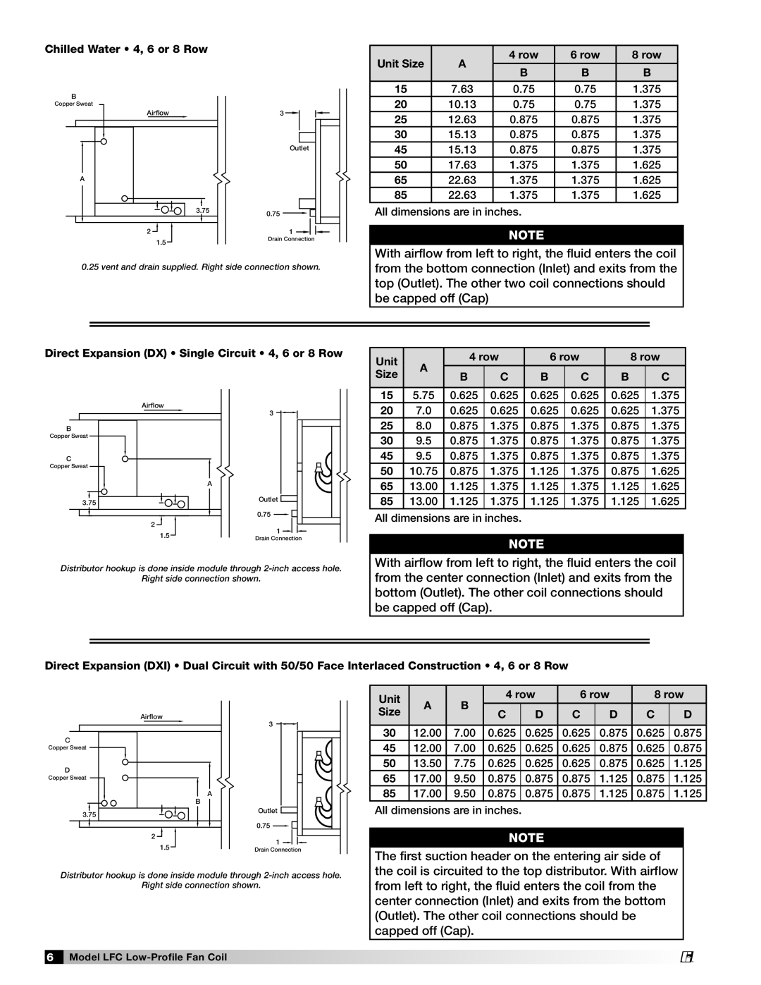
Chilled Water • 4, 6 or 8 Row

B

Copper Sweat

Airflow

A

3.75

2

1.5

3

Outlet

0.75

1

Drain Connection

Unit Size

A

4 row

6 row

8 row


B

B

B


15

7.63

0.75

0.75

1.375

20

10.13

0.75

0.75

1.375

25

12.63

0.875

0.875

1.375

30

15.13

0.875

0.875

1.375

45

15.13

0.875

0.875

1.375

50

17.63

1.375

1.375

1.625

65

22.63

1.375

1.375

1.625

85

22.63

1.375

1.375

1.625

All dimensions are in inches.

NOTE

0.25 vent and drain supplied. Right side connection shown.

With airflow from left to right, the fluid enters the coil from the bottom connection (Inlet) and exits from the top (Outlet). The other two coil connections should be capped off (Cap)

Direct Expansion (DX) • Single Circuit • 4, 6 or 8 Row

Unit

A


4 row


6 row


8 row


Size

B

C

B

C

B

C


Airflow

B

Copper Sweat

C

Copper Sweat

A

3.75

2

1.5

3

Outlet

0.75

1

Drain Connection

15

5.75

0.625

0.625

0.625

0.625

0.625

1.375

20

7.0

0.625

0.625

0.625

0.625

0.625

1.375

25

8.0

0.875

1.375

0.875

1.375

0.875

1.375

30

9.5

0.875

1.375

0.875

1.375

0.875

1.375

45

9.5

0.875

1.375

0.875

1.375

0.875

1.375

50

10.75

0.875

1.375

1.125

1.375

0.875

1.625

65

13.00

1.125

1.375

1.125

1.375

1.125

1.625

85

13.00

1.125

1.375

1.125

1.375

1.125

1.625

All dimensions are in inches.

NOTE

Distributor hookup is done inside module through 2-inch access hole.

Right side connection shown.

With airflow from left to right, the fluid enters the coil from the center connection (Inlet) and exits from the bottom (Outlet). The other coil connections should be capped off (Cap).

Direct Expansion (DXI) • Dual Circuit with 50/50 Face Interlaced Construction • 4, 6 or 8 Row

Airflow

C

Copper Sweat

D

Copper Sweat

A

B

3.75

2

1.5

3

Outlet

0.75

1

Drain Connection

Unit

A

B

4 row

6 row

8 row


Size

C

D

C

D

C

D


30

12.00

7.00

0.625

0.625

0.625

0.875

0.625

0.875

45

12.00

7.00

0.625

0.625

0.625

0.875

0.625

0.875

50

13.50

7.75

0.625

0.625

0.625

0.875

0.625

1.125

65

17.00

9.50

0.875

0.875

0.875

1.125

0.875

1.125

85

17.00

9.50

0.875

0.875

0.875

1.125

0.875

1.125

All dimensions are in inches.

NOTE

The first suction header on the entering air side of the coil is circuited to the top distributor. With airflow

Distributor hookup is done inside module through 2-inch access hole.

Right side connection shown.

from left to right, the fluid enters the coil from the center connection (Inlet) and exits from the bottom (Outlet). The other coil connections should be capped off (Cap).

6 Model LFC Low-Profile Fan Coil

®

Page 6
Image 6
Greenheck Fan LFC manual Chilled Water 4, 6 or 8 Row

LFC specifications

Greenheck Fan LFC is a prominent player in the realm of ventilation and air movement solutions, known for its innovative approach to fan technology. The LFC series offers a range of features specifically designed to enhance indoor air quality while maintaining energy efficiency. One of the standout aspects of the LFC series is its application in both commercial and industrial settings, providing versatile solutions for various ventilation requirements.

One of the main features of the Greenheck Fan LFC is its direct drive design. This configuration eliminates the need for belts and pulleys, reducing maintenance requirements and increasing reliability. The direct drive system also allows for quieter operation, making it ideal for environments where noise control is critical, such as schools and healthcare facilities. With a wide range of motor options available, users can select the most appropriate solution for their specific airflow and energy consumption needs.

The LFC series is engineered with high-efficiency impellers, which greatly enhance airflow performance while minimizing energy usage. These impellers are designed to optimize air movement, allowing the fans to operate more efficiently across different speed settings. This focus on efficiency is not only beneficial for reducing operational costs but also contributes to sustainability efforts by lowering energy consumption, which is increasingly important in today’s environmentally conscious market.

Moreover, the LFC series features advanced aerodynamic designs that help to streamline airflow, reducing turbulence and improving overall system efficiency. This design innovation leads to better performance in applications requiring precise ventilation control. The fans can be equipped with variable frequency drives (VFDs), enabling dynamic control over fan speed and further enhancing energy efficiency by adapting airflow to real-time demands.

Durability is another hallmark of the Greenheck Fan LFC. Constructed from high-quality materials that resist corrosion and wear, these fans are built to withstand the rigors of harsh environments, ensuring long service life. Additionally, the LFC series can be customized with various coatings and finishes, making them suitable for diverse industrial applications.

In summary, the Greenheck Fan LFC series combines advanced technology with user-centric design. Its key features—such as direct drive systems, high-efficiency impellers, advanced aerodynamics, and robust construction—position it as a leading choice for effective and efficient ventilation solutions. Whether employed in commercial spaces or heavy-duty industrial applications, the LFC fans represent a commitment to quality and performance in air movement technology.