System Start-Up

For proper unit function and safety, follow everything in this start-up procedure in the order presented. This is to be done after the electrical connections are complete.

PRE-START CHECK LIST

1.Disconnect and lock-out all power switches to fan.

2.Check all fasteners, set screws and locking collars on the fan, bearings, drive, motor base and accessories for tightness.

3.Rotate the fan wheel by hand and assure no parts are rubbing.

4.Check the V-belt drive for proper alignment and tension.

special tools required

Voltage Meter

Tachometer

Amperage Meter

1.Check Voltage

Before starting the unit, compare the supplied voltage with the unit’s nameplate voltage and the motor voltage. Units are not provided with thermal overload protection unless a control center has been ordered with the unit or the motor has been selected with thermal overload protection.

2. Check Blower Rotation

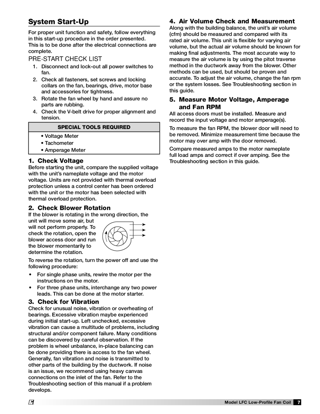
If the blower is rotating in the wrong direction, the unit will move some air, but

will not perform properly. To

TION


A


T


O


AIRFLOW

check the rotation, open the

R


blower access door and run


the blower momentarily to


determine the rotation.


To reverse the rotation, turn the power off and use the following procedure:

For single phase units, rewire the motor per the instructions on the motor.

For three phase units, interchange any two power leads. This can be done at the motor starter.

3. Check for Vibration

Check for unusual noise, vibration or overheating of bearings. Excessive vibration maybe experienced during initial start-up. Left unchecked, excessive vibration can cause a multitude of problems, including structural and/or component failure. Many conditions can be discovered by careful observation. If the problem is wheel unbalance, in-place balancing can be done providing there is access to the fan wheel. Generally, fan vibration and noise is transmitted to other parts of the building by the ductwork. If noise is an issue, we recommend using heavy canvas connections on the inlet of the fan. Refer to the Troubleshooting section of this manual if a problem develops.

4. Air Volume Check and Measurement

Along with the building balance, the unit’s air volume (cfm) should be measured and compared with its rated air volume. This unit is flexible for varying air volume, but the actual air volume should be known for making final adjustments. The most accurate way to measure the air volume is by using the pitot traverse method in the ductwork away from the blower. Other methods can be used, but should be proven and accurate. To adjust the air volume, change the fan rpm or the system losses. See Troubleshooting section in this guide.

5. Measure Motor Voltage, Amperage and Fan RPM

All access doors must be installed. Measure and record the input voltage and motor amperage(s).

To measure the fan RPM, the blower door will need to be removed. Minimize measurement time because the motor may over amp with the door removed.

Compare measured amps to the motor nameplate full load amps and correct if over amping. See the Troubleshooting section in this guide.

®

Model LFC Low-Profile Fan Coil 7

Page 7
Image 7
Greenheck Fan LFC manual System Start-Up

LFC specifications

Greenheck Fan LFC is a prominent player in the realm of ventilation and air movement solutions, known for its innovative approach to fan technology. The LFC series offers a range of features specifically designed to enhance indoor air quality while maintaining energy efficiency. One of the standout aspects of the LFC series is its application in both commercial and industrial settings, providing versatile solutions for various ventilation requirements.

One of the main features of the Greenheck Fan LFC is its direct drive design. This configuration eliminates the need for belts and pulleys, reducing maintenance requirements and increasing reliability. The direct drive system also allows for quieter operation, making it ideal for environments where noise control is critical, such as schools and healthcare facilities. With a wide range of motor options available, users can select the most appropriate solution for their specific airflow and energy consumption needs.

The LFC series is engineered with high-efficiency impellers, which greatly enhance airflow performance while minimizing energy usage. These impellers are designed to optimize air movement, allowing the fans to operate more efficiently across different speed settings. This focus on efficiency is not only beneficial for reducing operational costs but also contributes to sustainability efforts by lowering energy consumption, which is increasingly important in today’s environmentally conscious market.

Moreover, the LFC series features advanced aerodynamic designs that help to streamline airflow, reducing turbulence and improving overall system efficiency. This design innovation leads to better performance in applications requiring precise ventilation control. The fans can be equipped with variable frequency drives (VFDs), enabling dynamic control over fan speed and further enhancing energy efficiency by adapting airflow to real-time demands.

Durability is another hallmark of the Greenheck Fan LFC. Constructed from high-quality materials that resist corrosion and wear, these fans are built to withstand the rigors of harsh environments, ensuring long service life. Additionally, the LFC series can be customized with various coatings and finishes, making them suitable for diverse industrial applications.

In summary, the Greenheck Fan LFC series combines advanced technology with user-centric design. Its key features—such as direct drive systems, high-efficiency impellers, advanced aerodynamics, and robust construction—position it as a leading choice for effective and efficient ventilation solutions. Whether employed in commercial spaces or heavy-duty industrial applications, the LFC fans represent a commitment to quality and performance in air movement technology.