Extreme Series Bandsaw
Ss ,EAD from Leadbased PAINTS
Table of Contents
NdjgBVXcZ
Introduction
Manual Accuracy
Contact Info
Bdidg 9jhiEdgi =c\ZY9ddg Aic\nZ7dai
Identification G0514X
8jiic\=Z\iHXVaZ
Identification G0514X2/G0514X2B/G0514X3
Model Number G0514X G0514X2 G0514X2B G0514X3
7aVYZ
7aVYZHeZZYh
IVWaZIai AZi*!G\i*
BVmbjb8jiic\=Z\i BVmbjb8VeVXinAZid
Lidji ZVgc\ egdiZXidc XVc XVjhZ eZgbVcZci ZVgc\adhh#
Safety
Safety Instructions for Machinery
DWhZgkc\ bVXcZgn id gZYjXZ iZ gh` d ZnZ
ZghWZXdbZVYhigVXidc#
Children & BYSTANDERS. @ZZe XaYgZc
Additional Safety for Bandsaws
Circuit Information
Power Supply
Availability
Full-Load Current Rating
Minimum Gauge Size 14 AWG
G0514X, G0514X2, G0514X2B Grounding Requirements
G0514X, G0514X2, G0514X2B Extension Cords
VcY%*&M#
G0514X3 Extension Cords
G0514X3 Phase Converter Caution
G0514X3 Circuit Requirements
G0514X3 Grounding Instructions
G0514X3 Conversion
To rewire the Model G0514X3 for 440V opera- tion
XdkZg#
Description Qty
Setup
Needed for Setup
Unpacking
G0514X Inventory
Crate Contents & 11 Qty
Hardware and Tools not shown Qty
G0514X2 & G0514X3 Inventory
Crate Contents -14 Qty
G0514X2B
Crate Contents -17 Qty
Hardware Recognition Chart
Floor Load
Clean Up
Placement Location
Site Considerations
JcWdaiiZWVcYhVlgdbiZeVaaZi#
To move and place the bandsaw using the eye bolt
To move and place the bandsaw using wood shims
Moving & Placing Base Unit
Guide Post Handwheel
MountingAssembly
To install the table
Bolting to Concrete Floors
Model G0514X2, G0514X2B, G0514X3
To center track the blade
Blade Tracking
Changes in the blade tension may change the blade tracking
AdX`AZkZg
Positive Stop
Installing Positive Stop
Positioning Positive Stop
To connect a dust collection hose
Installing Fence G0514X, -X2
To install the fence
Dust Collection
ChiVaaZYgVaeVY#
Installing Foot Brake G0514X2
Installing Fence G0514X2B
G0514X3 Power Connection
G0514X, -X2, & X2B Power Connection
To test run the machine
Test Run
@Zn
23#
Tensioning Blade
dcPage 30#
To tension the bandsaw blade
Adjusting Upper Support Bearings
Adjusting Support Bearings
Guide Bearings
Adjusting Blade
Adjusting Lower Support Bearings
To adjust the upper and lower blade guides
@cdW HXgZl
7aVYZjYZ
7ZVgc\h 6YjhibZci
@cjgaZY
Aligning Fence
Aligning Table
To align the fence parallel with the miter slot
To calibrate the miter gauge
Fence Pointer Calibration
Miter Gauge
To calibrate the pointer
Basic Controls
Operations
EdlZgHliX @Zn Dc7jiidc
Quick Release Blade Tension Lever
Front Controls
Rear Controls
Blade Tension Handwheel/IZchdchWaVYZ
Table Tilt Handwheel G0514X2, G0514X2B
Operation Overview
Basic Cutting Tips
G0514X2B Motor Brake
8jiic\lddYlibcdglVgec\#
Workpiece Inspection
G0514X Table Tilt
Foot Brake Table Tilt
7aVYZjVgY JYZEdhi
To adjust the blade guide assembly on the guide post
Guide Post
G0514X2, G0514X2B, & G0514X3 Table Tilt
To make a rip cut
Fine Tune Tracking
Ripping
To fine tune the tracking
To make a 90˚ crosscut
CrosscuttingResawing
To resaw a workpiece
Cutting Curves
Stacked Cuts Blade Speed
To adjust the blade speed
To complete a stacked cut
Blade Length
Blade Information
Blade Width
Blade Breakage
Tooth Style
Tooth Pitch
Blade Care
Most common causes of blade breakage are
Installing Blade
Blade Changes
Removing Blade
G7315Z-Super Heavy-Duty EAB 8AJ Mobile Base
Accessories
G1094-Bandsaw Power Feeder with Fence, Single-Phase
G1163-1HP Dust Collector
6Yjhihgdb+id*¿-#
EAB8AJ Roller Stands G8984-Single Roller Stand
6Yjhihgdb+*¿-id*#
G8985-5 Roller Stand
Maintenance
Lubricant Frequency Qty
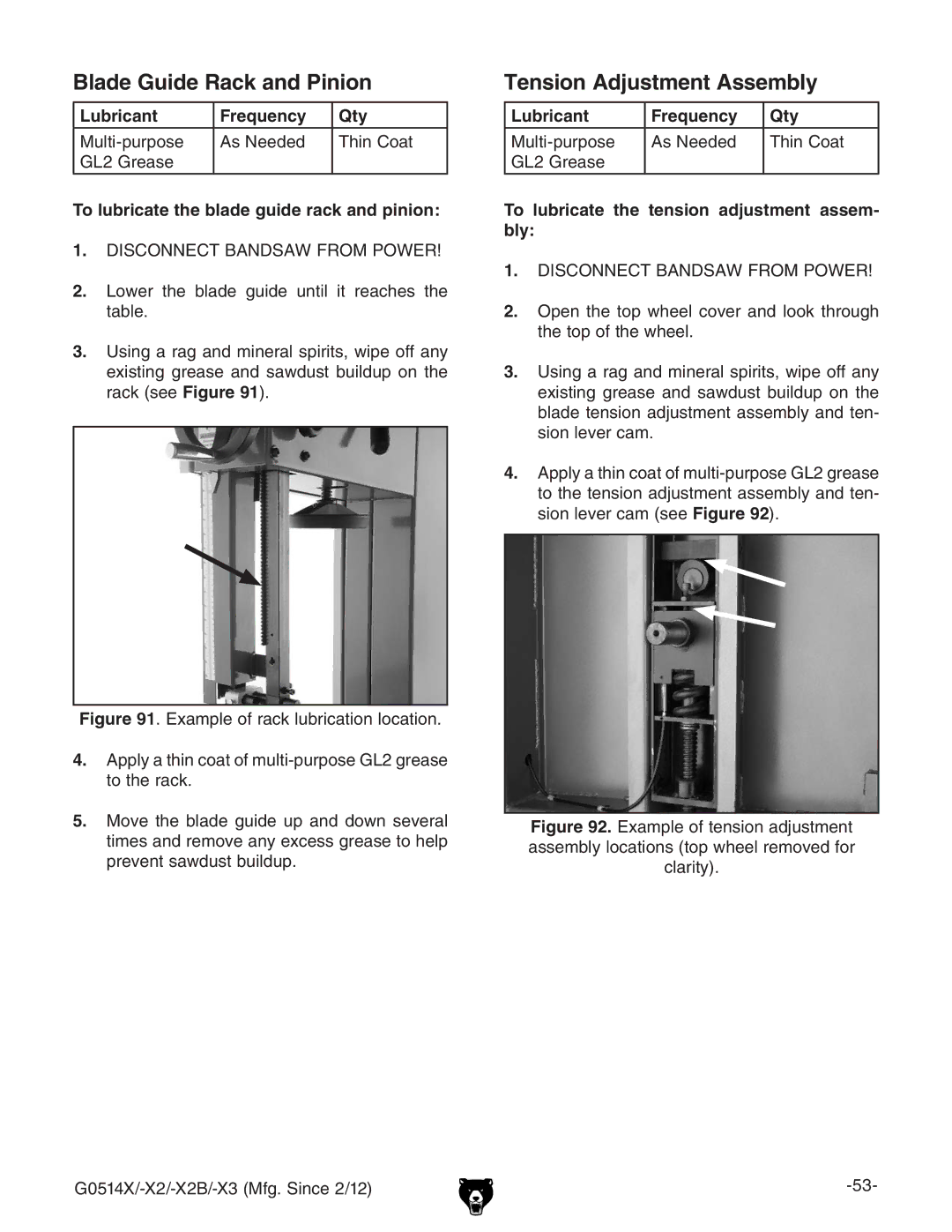
Tension Adjustment Assembly
To lubricate the tension adjustment assem- bly
Blade Guide Rack and Pinion
VcYhVlYjhiWjaYjegdbiZgVX`#
To lubricate the table tilt rack and pinion assembly
Trunnion
BdkZiZiVWaZjeidihbVmbjb*ßVc\aZ
Troubleshooting
Service
Hnbeidb EdhhWaZ8VjhZ EdhhWaZHdajidc
60#
39#
JhZ#
Tools Needed Qty
Checking V-Belt
Tensioning V-Belt
To check the V-belt
Tools NeededQty
Replacing V-Belt
To replace the V-belt
To shift the table
Blade Lead
To correct blade lead
To skew your fence
ChangesdcPage 49#
To adjust the brushes
To adjust the tension lever
Brush
AddhZc ZVX d iZ djg hXgZlh hdlc c
Adjusting Guide Post Travel
Tools Needed
JYZEdhi
Hb7 GVbZ
I\iZciZhXgZlhhdlcc #
9hiVcXZ7
AddhZc iZ djg hXgZlh hdlc c Figure
Checking Coplanarity
Aligning Wheels
Components and Hardware Needed Qty
9ZgZcXZ7ZilZZc
Shimming Upper Wheel
LZZaDjid 6YjhibZci
Iai 7diidbIai
Adjusting Lower Wheel
To adjust the lower wheel
Iai IdeIai
XdbedcZcih#
Wiring
Wiring Safety Instructions
Shock HAZARD. Ldg`c\dclgc\iVihXdc
G0514X Wiring Diagram
G0514X2 Wiring Diagram
Magnetic Switch Assembly Control Panel Viewed from Behind
G0514X2B Wiring Diagram
Magnetic Switch Assembly Control Panel Viewed from Behind
G0514X3 Wiring Diagram
G0514X Main
Parts
Description
G0514X Main Parts List
G0514X Fence/Guides
G0514X Fence/Guide Parts List
Description
G0514X2 & G0514X3 Main
G0514X2 & G0514X3 Main Parts List
G0514X3 440V Magnetic Switch
G0514X3 Power Connection Junction Box
G0514X2 220V Magnetic Switch
G0514X3 220V Magnetic Switch
G0514X2 & G0514X3 Fence & Guides
G0514X2 & G0514X3 Fence & Guides Parts List
Lock Wedge
G0514X2 & G0514X3 Labels
Main
G0514X2B Main Parts List
G0514X2B Fence & Guides
G0514X2B Fence & Guides Parts List
Lower Guide Bracket
G0514X2B Labels
10. 8dbbZcih
$5342!, .# 0/ /8 %,,.!- 7!
EaVXZ HiVbe =ZgZ
22!.49 !.$ 2%452.3
Order Hours a DAY