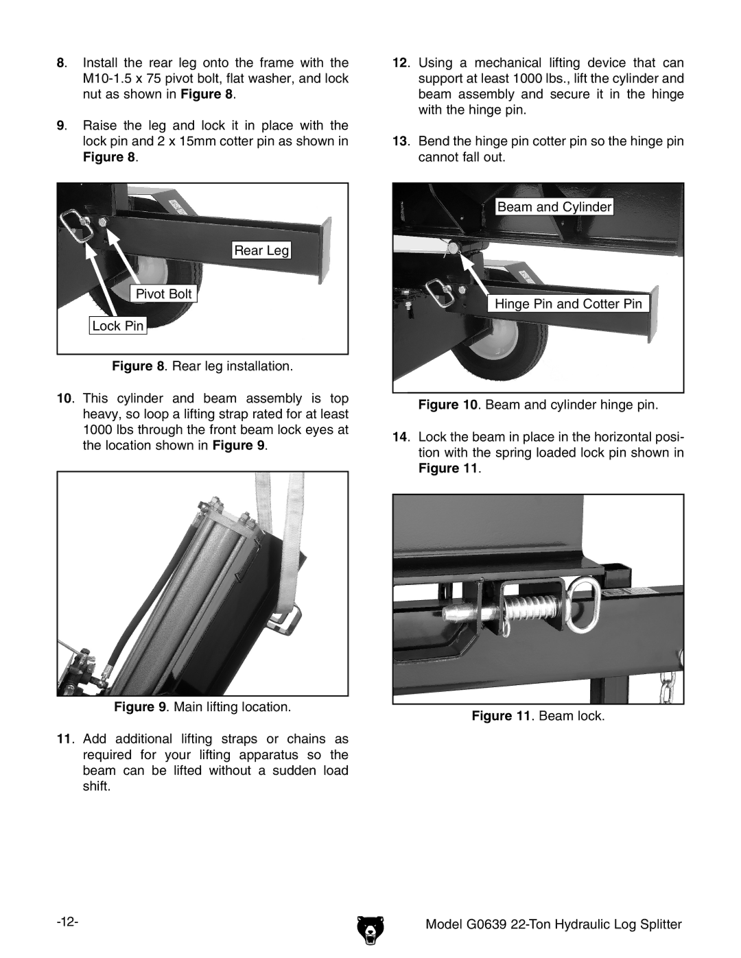
8. Install the rear leg onto the frame with the M10-1.5 x 75 pivot bolt, flat washer, and lock nut as shown in Figure 8.
9. Raise the leg and lock it in place with the lock pin and 2 x 15mm cotter pin as shown in Figure 8.
Rear Leg
Pivot Bolt
Lock Pin
Figure 8. Rear leg installation.
10. This cylinder and beam assembly is top heavy, so loop a lifting strap rated for at least 1000 lbs through the front beam lock eyes at the location shown in Figure 9.
Figure 9. Main lifting location.
11. Add additional lifting straps or chains as required for your lifting apparatus so the beam can be lifted without a sudden load shift.
-12-
12. Using a mechanical lifting device that can support at least 1000 lbs., lift the cylinder and beam assembly and secure it in the hinge with the hinge pin.
13. Bend the hinge pin cotter pin so the hinge pin cannot fall out.
Beam and Cylinder
Hinge Pin and Cotter Pin
Figure 10. Beam and cylinder hinge pin.
14. Lock the beam in place in the horizontal posi- tion with the spring loaded lock pin shown in Figure 11.
Figure 11. Beam lock.
Model G0639 22-Ton Hydraulic Log Splitter