Upper Guides
Normally Steps
1.Loosen the bearing guide shaft lock nuts.
2.The bearing guides are mounted on an eccentric shaft. With a regular screwdriver, rotate the guides away from the blade.
3.Loosen the cap screw holding the rear sup- port bearing in place and slide the rear sup- port bearing away from the blade.
4.Loosen the cap screw holding the blade guide assembly in place and slide it back away from the blade.
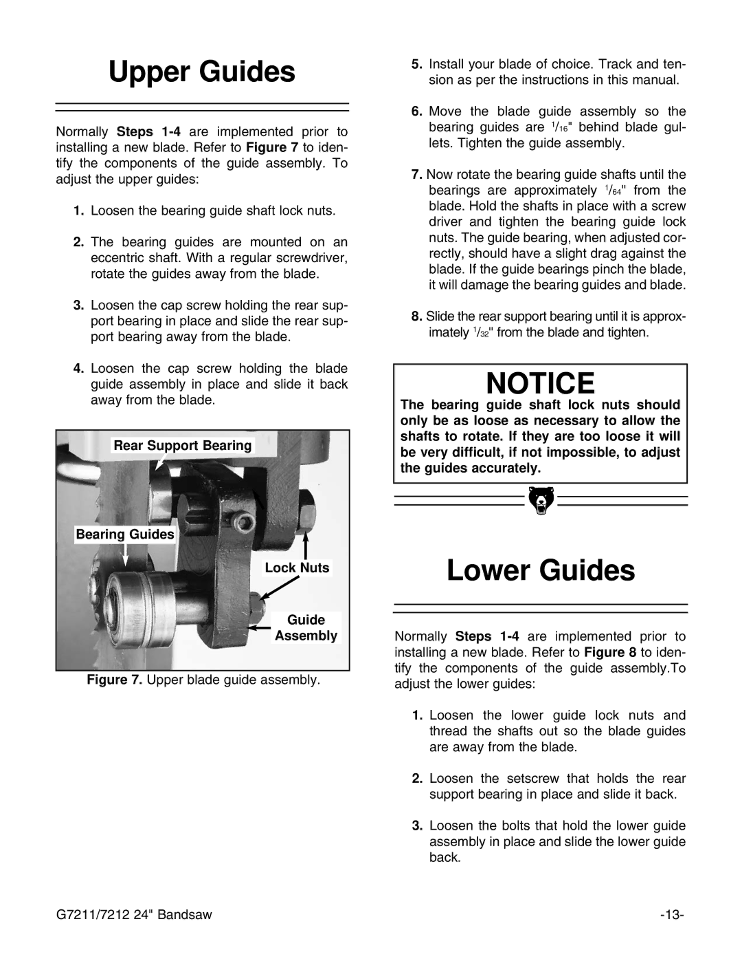
Rear Support Bearing
Bearing Guides
Lock Nuts
Guide
Assembly
Figure 7. Upper blade guide assembly.
5.Install your blade of choice. Track and ten- sion as per the instructions in this manual.
6.Move the blade guide assembly so the bearing guides are 1/16" behind blade gul- lets. Tighten the guide assembly.
7.Now rotate the bearing guide shafts until the bearings are approximately 1/64'' from the blade. Hold the shafts in place with a screw driver and tighten the bearing guide lock nuts. The guide bearing, when adjusted cor- rectly, should have a slight drag against the blade. If the guide bearings pinch the blade, it will damage the bearing guides and blade.
8.Slide the rear support bearing until it is approx- imately 1/32'' from the blade and tighten.
NOTICE
The bearing guide shaft lock nuts should only be as loose as necessary to allow the shafts to rotate. If they are too loose it will be very difficult, if not impossible, to adjust the guides accurately.
Lower Guides
Normally Steps
1.Loosen the lower guide lock nuts and thread the shafts out so the blade guides are away from the blade.
2.Loosen the setscrew that holds the rear support bearing in place and slide it back.
3.Loosen the bolts that hold the lower guide assembly in place and slide the lower guide back.
G7211/7212 24" Bandsaw |