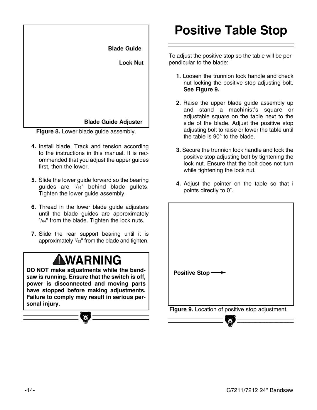
Blade Guide
Lock Nut
Blade Guide Adjuster
Figure 8. Lower blade guide assembly.
4.Install blade. Track and tension according to the instructions in this manual. It is rec- ommended that you adjust the upper guides first, then the lower.
5.Slide the lower guide forward so the bearing guides are 1/16" behind blade gullets. Tighten the lower guide assembly.
6.Thread in the lower blade guide adjusters until the blade guides are approximately 1/64'' from the blade. Tighten the lock nuts.
7.Slide the rear support bearing until it is approximately 1/32'' from the blade and tighten.
DO NOT make adjustments while the band- saw is running. Ensure that the switch is off, power is disconnected and moving parts have stopped before making adjustments. Failure to comply may result in serious per- sonal injury.
Positive Table Stop
To adjust the positive stop so the table will be per- pendicular to the blade:
1.Loosen the trunnion lock handle and check nut locking the positive stop adjusting bolt.
See Figure 9.
2.Raise the upper blade guide assembly up and stand a machinistÕs square or adjustable square on the table next to the side of the blade. Adjust the positive stop adjusting bolt to raise or lower the table until the table is 90¡ to the blade.
3.Secure the trunnion lock handle and lock the positive stop adjusting bolt by tightening the lock nut. Ensure that the bolt does not turn while tightening the lock nut.
4.Adjust the pointer on the table so that i points directly to 0û.
Positive Stop 
Figure 9. Location of positive stop adjustment.
|
|
|
|
|
|
|
|
|
|
|
|
|
|
|
|
|
|
|
|
|
|
|
|
|
|
|
|
|
|
|
| G7211/7212 24" Bandsaw | ||