Make sure proper turning clearance exists between the bearing casing and the locking yoke before operation. Serious personal injury or damage to the lathe and collet closer can occur if there is contact. Rotate draw tube and check for clearance. DO NOT make adjustments, remove workpiece or open back cover of lathe while the machine is in motion.
Locking Stroke
To adjust the locking stroke on your collet closer:
1.Position the locking pawls so they are in the correct position on the cam as shown in Figure 12.
Locking Pawl
Figure 12. Locking pawls in locked position
on the cam lobe.
2.Secure the 38mm spanner nut against the outboard side of the bearing housing and then secure the 30mm spanner nuts against the 38mm spanner nut as shown in Figure 13. NoteÑBe sure that the 30mm spanner with the setscrew is on the outside, with the setscrew accessible.
3.The two 30mm spanners define the stroke distance. Secure the setscrew in the outer 30mm spanner nut to lock the stroke dis- tance.
38mm spanner
30mm spanners
Figure 13. Spanner nut positioning for locking
stroke adjustment.
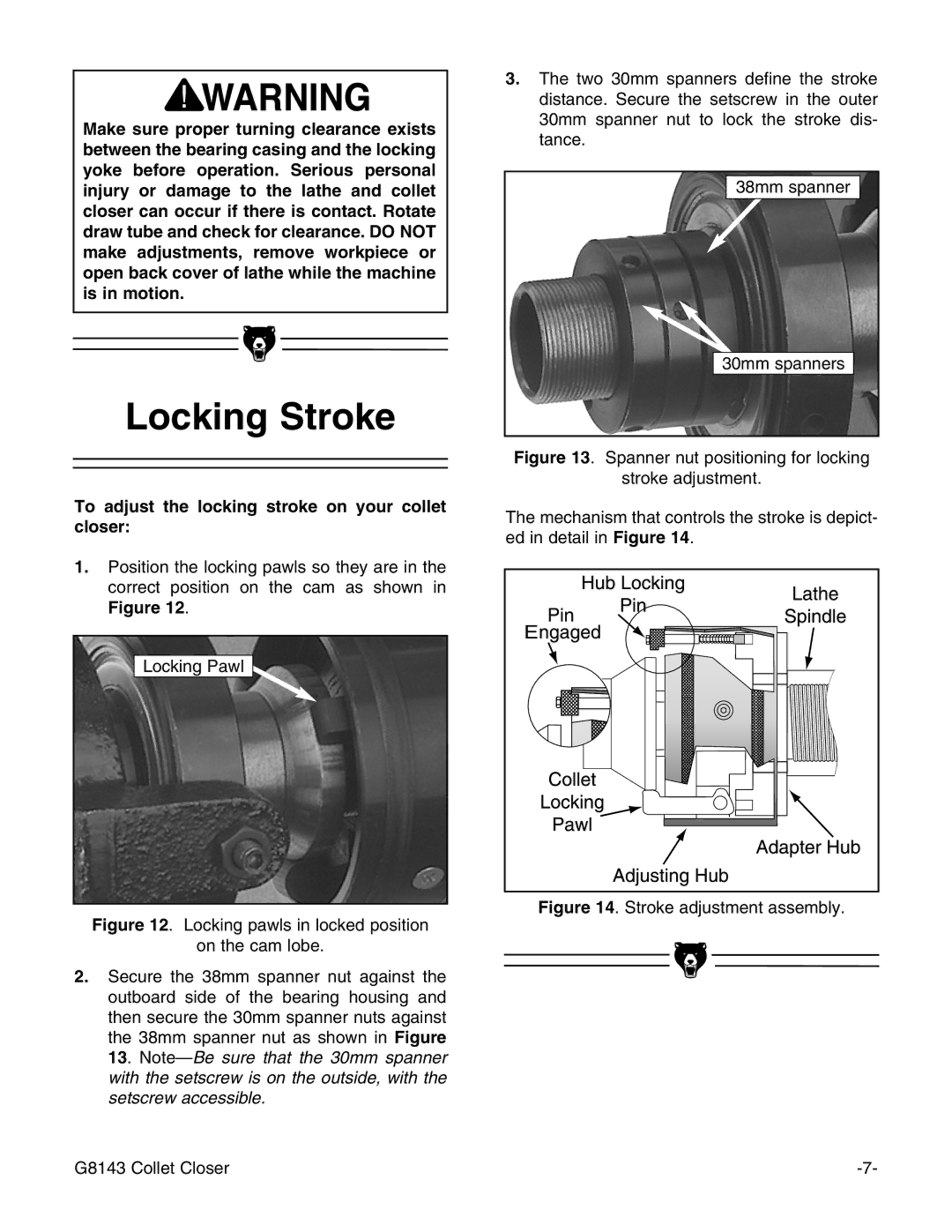
The mechanism that controls the stroke is depict- ed in detail in Figure 14.
E |
Figure 14. Stroke adjustment assembly.
G8143 Collet Closer |
