III) INSTALLATION


IMPORTANT:

Unpacking the Water Heater


This water heater must be installed strictly in accordance


with the instructions enclosed, and local electrical, fuel


WARNING


and building codes. It is possible that connections to the

Excessive Weight Hazard


water heater, or the water heater itself, may develop

Use two or more people to move and install


leaks. IT IS THEREFORE IMPERATIVE that the water

water heater. Failure to do so can result in


heater be installed so that any leakage of the tank or relat-


ed water piping is directed to an adequate drain in such a

back or other injury.


manner that it cannot damage the building, furniture, floor

Important: Do not remove any permanent instructions,


covering, adjacent areas, lower floors of the structure or

labels, or the data label from outside of the water heater or


other property subject to water damage. This is particular-

on the inside of panels.


ly important if the water heater is installed in a multi-story


building, on finished flooring or carpeted surfaces. GSW

• Remove exterior packaging and place installation com-


WILL NOT ASSUME ANY LIABILITY for damage caused

ponents aside.


by water leaking from the water heater, pressure relief

• Inspect all parts for damage prior to installation and


valve, or related fittings. Select a location as centralized

start-up.


within the piping system as possible. In any location

• Completely read all instructions before attempting to


selected, it is recommended that a suitable drain pan be

assemble and install this product.


installed under the water heater. This pan must limit the

If you observe damage to the water heater or any of its com-


water level to a MAXIMUM depth of 45mm (1 3/4 in.) and

ponents, DO NOT ASSEMBLE OR INSTALL IT OR MAKE


have a diameter that is a minimum of 50mm (2 in.) greater

ANY ATTEMPT TO FIX THE DAMAGED PART(S). Contact


than the diameter of the water heater. Suitable piping shall

the place of purchase for further instructions.


connect the drain pan to a properly operating floor drain.

• After installation, dispose of packaging material in the


proper manner.


CAUTION: When this water heater is installed directly on

Location


carpeting, carpeting must be protected by a metal or wood


panel beneath the appliance extending beyond the full width

Generally, the location selected should be as close to the


and depth of the appliance by at least 76mm (3 in.) in any

wall as practical and as centralized with the piping system


direction, or if the appliance is installed in an alcove or clos-

as possible. Heater should be located in an area not subject


et, the entire floor must be covered by the panel. The panel

to freezing temperatures.


must be strong enough to carry the weight of the heater


when full of water. Failure to heed this warning may result in

The water heater should be located so that the controls and


a fire hazard.

drain are easily accessible.


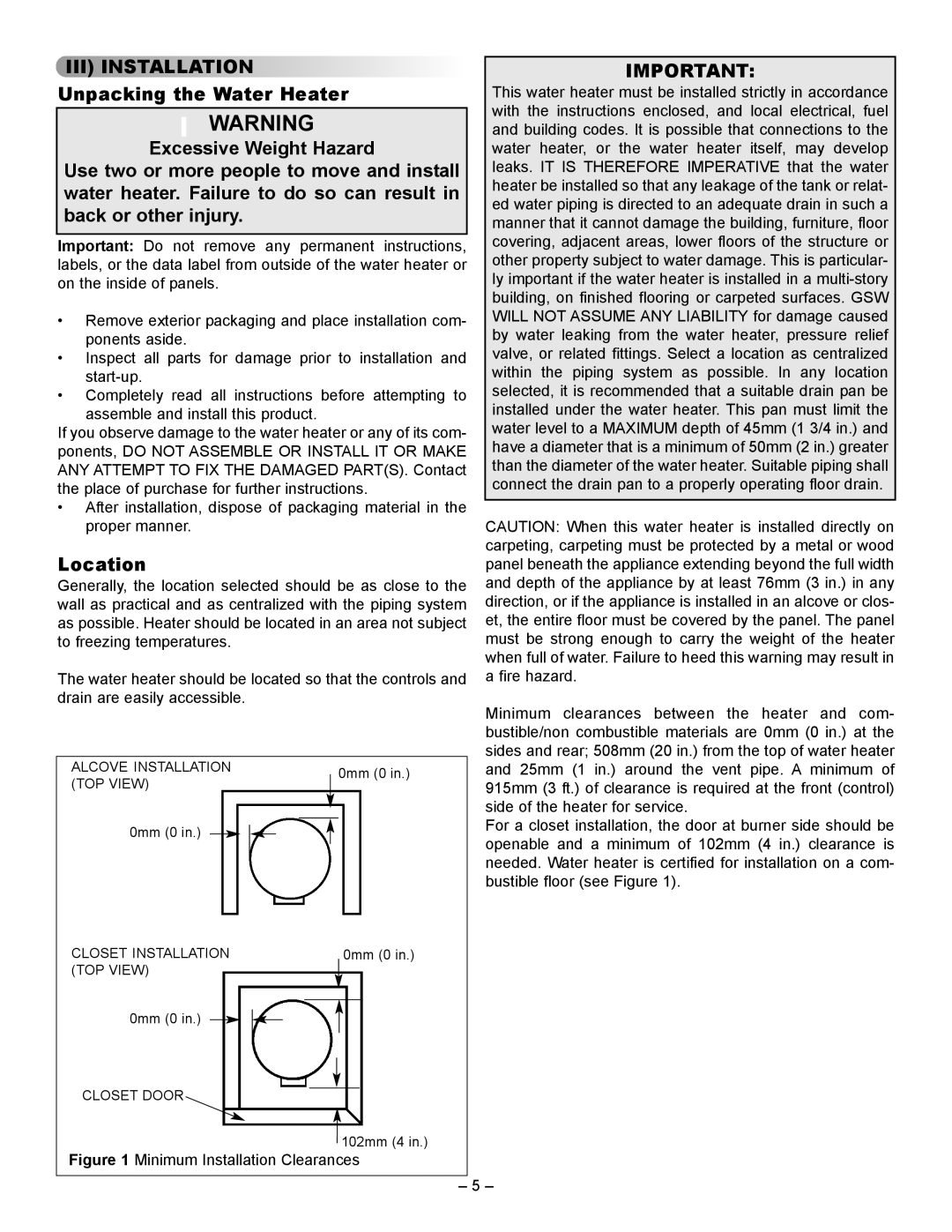
Minimum clearances between the heater and com-


bustible/non combustible materials are 0mm (0 in.) at the


sides and rear; 508mm (20 in.) from the top of water heater

ALCOVE INSTALLATION


0mm (0 in.)


and 25mm (1 in.) around the vent pipe. A minimum of

(TOP VIEW)


915mm (3 ft.) of clearance is required at the front (control)


side of the heater for service.

0mm (0 in.)


For a closet installation, the door at burner side should be


openable and a minimum of 102mm (4 in.) clearance is


needed. Water heater is certified for installation on a com-


bustible floor (see Figure 1).

CLOSET INSTALLATION


0mm (0 in.)


(TOP VIEW)


0mm (0 in.)


CLOSET DOOR


102mm (4 in.)


Figure 1 Minimum Installation Clearances

– 5 –

Page 5
Image 5
GSW 61009 REV. C (09-03) manual III Installation

61009 REV. C (09-03) specifications

The GSW 61009 REV. C (09-03) is a prominent model within the realm of electrical distribution and protection equipment, specifically engineered to deliver reliable performance in various industrial applications. This device is particularly tailored for low-voltage electrical networks, ensuring safety, efficiency, and longevity in operations.

One of the main features of the GSW 61009 REV. C is its advanced circuit protection capabilities. Equipped with residual current devices (RCDs), it is designed to prevent electric shocks and electrical fires, enhancing overall safety standards in any installation. The device also incorporates circuit breakers that automatically disconnect electrical circuits during overloads or short circuits, preventing potential equipment damage and safeguarding personnel.

The GSW 61009 REV. C also exhibits exceptional thermal and mechanical stability, attributed to its high-quality materials and robust engineering. It is built to withstand harsh operational environments, ensuring reliable functionality even under challenging conditions. This durability is crucial for industries such as manufacturing, construction, and energy sectors, where equipment often faces extreme temperatures and vibrations.

Technologically, the GSW 61009 REV. C is designed with user-friendly features, making installation and maintenance straightforward for technicians. It includes clear labeling and intuitive interfaces for easy operation, which simplifies the process of monitoring and troubleshooting. Furthermore, its modular design allows for easy upgrades and expansions, accommodating evolving electrical needs without the need for a complete system overhaul.

The GSW 61009 REV. C also complies with international safety standards, ensuring that it meets rigorous guidelines for electrical devices. This certification not only reinforces the product’s reliability but also builds trust with end-users aware of safety compliance in electrical installations.

Additionally, energy efficiency is a priority with the GSW 61009 REV. C, as it minimizes power loss during operation, contributing to lower energy costs. This focus on efficiency aligns with global sustainability efforts, positioning the product as a responsible choice for modern electrical applications.

In summary, the GSW 61009 REV. C (09-03) stands out as an essential component in electrical systems, offering optimal protection, durability, and efficiency. Its features and technologies make it a preferred choice for industries requiring robust and reliable electrical distribution solutions. The combination of safety, ease of use, and compliance with standards underscores its importance in safeguarding both people and infrastructure in the electrical landscape.