Manuals
/
Hafler
/
Computer Equipment
/
Computer Monitor
Hafler
TRM6.1CE
manual
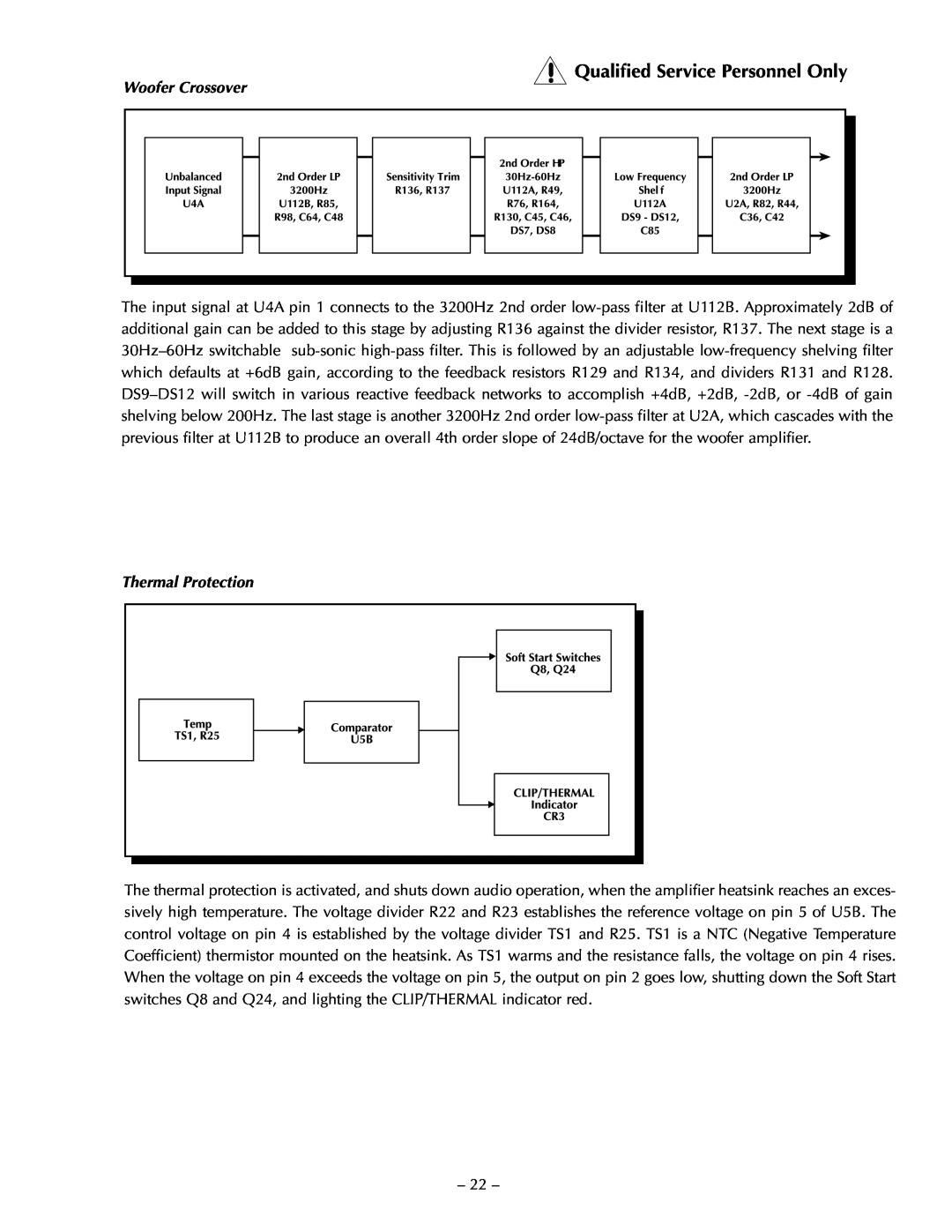
Qualified Service Personnel Only, Woofer Crossover, Thermal Protection
Models:
TRM6.1
TRM6.1CE
1
31
36
36
Download
36 pages
50.06 Kb
28
29
30
31
32
33
34
35
Specs
Install
Parts list
Schematic Diagram
Clipping Indicator
Warranty
Wave Guide Assembly
Phase Coherent
CLEANING and MAINTENANCE
Amplifier Replacement
Page 31
Image 31
Page 30
Page 32
Page 31
Image 31
Page 30
Page 32
Contents
Page
to the above Directives and Standards
EN60065 safety
2-channel Audio Power Amplifier/Speaker
Declaration of Conformity
Power Rating
PERFORMANCE SPECIFICATIONS
Dimensions
Net Weight
C A U T I O N
NOTICE - IMPORTANT SAFETY INFORMATION
ESPAÑOL
ADVERTENCIA - INFORMACION DE SEGURIDAD IMPORTANTE
RANÇAIS
ATTENTION INFORMATIONS IMPORTANTES DE SÉCURITÉ
DEUTSCH
ACHTUNG - WICHTIGE SICHERHEITS - INFORMATIONEN
ITALIANO
NOTARE - IMPORTANTI INFORMAZIONI SULLA SICUREZZA
SERVICE REFERENCE
TABLE OF CONTENTS
INSTALLATION
SCHEMATIC DIAGRAMS
INTRODUCTION
TECHNICAL DESIGN FEATURES
Amplifie
MEHSA
Transana
MOSFET Devices
Tweete
Phase Coherent
Wave Guide
Shielded Magnet
Tweeter Wave Guide Status LED
Balanced Input Unbalanced Input Input Switch Sensitivity
Front Panel View
Rear Panel View
OPTIMUM
INSTALLATION
LOCATION
INADEQUATE
INPUTFROM SOURCE Pin 1 = GND Pin 2 = + Pin 3 = GND
XLR Balanced Input
INPUTFROM SOURCE Pin 1 = GND Pin 2 = + Pin 3 =
XLR Unbalanced Input
NOTES Unless specified otherwise 1. All resistors in ohms
SCHEMATIC DIAGRAM
2. All capacitors in microfarads 3. Channel 1 only shown
Qualified Service Personnel Only
NOTES Unless specified otherwise 1. All resistors in ohms
SCHEMATIC DIAGRAM
2. All capacitors in microfarads 3. Channel 1 only shown
Qualified Service Personnel Only
SCHEMATIC Diagram
PC BOARD LAYOUT
+1dB Input
OPERATION
INPUT SENSITIVITY
+4dB Input
+2dB
with the same type and rating as indicated in the parts list
BASS SHELVING
+4dB
COLOR
Power on
POWER SWITCH
CLEANING and MAINTENANCE
PART #
PARTS LIST
DESIGNATOR
VALUE
RES 280 OHM 1/10W 1%
MODEL TRM6.1CE 230 VAC 50/60 Hz
TRM6.1 FUNCTIONAL BLOCK DIAGRAM
CALIBRATION
SERVICE REFERENCE
CIRCUIT OPERATION
transana Implementation
Tweeter Crossover
Input Circuit
Thermal Protection
Woofer Crossover
On Indicator
Clipping Indicator
Power Switch
Wave Guide Assembly
TWEETER REPLACEMENT
CAUTION Reconnect wires as indicated in each diagram
TRANSFORMER REPLACEMENT
Qualified Service Personnel Only
AMPLIFIER REPLACEMENT
CAUTION Reconnect wires as indicated in diagram
What is NOT Covered
SERVICE POLICY AND LIMITED WARRANTY
Length of Warranty
What is Covered
HAFLER A DIVISION OF
MADE IN THE USA
LIT 11382 11/00 E.W.R
Top
Page
Image
Contents