Installation Manual For Indoor Unit
(d)When constructing drain piping for several units, position the common pipe about 100 mm below the drain outlet of each unit as shown in the sketch. Use
(e)Be sure to provide heat insulation to hard PVC pipes of indoor placement.
(f)Do not ever provide an air vent.
(g)Avoid positioning the drain piping outlet at a place where generation of odor may be stimulated. Do not lead the drain piping direct into a sewer from where sulfur gas may generate.
Secure the elevation as high as possible (approx. 100 mm)
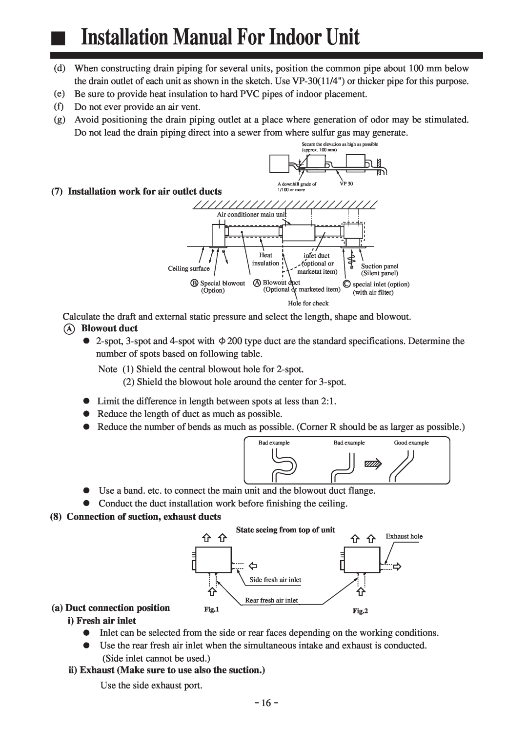
(7) Installation work for air outlet ducts
A downhill grade of | VP 30 |
1/100 or more |
|
Air conditioner main unit
| Heat | inlet duct |
| |
Ceiling surface | insulation | (optional or | Suction panel | |
marketat item) | (Silent panel) | |||
| ||||
B Special blowout | A Blowout duct | C | special inlet (option) | |
(Option) | (Optional or marketed item) | (with air filter) | ||
|
|
| ||
Hole for check
Calculate the draft and external static pressure and select the length, shape and blowout.
ABlowout duct
![]() 200 type duct are the standard specifications. Determine the number of spots based on following table.
200 type duct are the standard specifications. Determine the number of spots based on following table.
Note (1) Shield the central blowout hole for
(2) Shield the blowout hole around the center for
Limit the difference in length between spots at less than 2:1. Reduce the length of duct as much as possible.
Reduce the number of bends as much as possible. (Corner R should be as larger as possible.)
Bad example | Bad example |
| Good example |
|
|
|
|
|
|
|
|
Use a band. etc. to connect the main unit and the blowout duct flange.
Conduct the duct installation work before finishing the ceiling.
(8) Connection of suction, exhaust ducts
|
| State seeing from top of unit |
|
| Exhaust hole |
|
| Side fresh air inlet |
(a) Duct connection position |
| Rear fresh air inlet |
Fig.1 | Fig.2 |
i) Fresh air inlet
Inlet can be selected from the side or rear faces depending on the working conditions. Use the rear fresh air inlet when the simultaneous intake and exhaust is conducted. (Side inlet cannot be used.)
ii)Exhaust (Make sure to use also the suction.) Use the side exhaust port.
16