 NAME OF PARTS
10 | 11 |
| 1 |
|
|
|
| POWER | 4 |
|
|
| OPER | 5 |
|
| 3 | TIMER | 6 |
|
| COMP | 7 | |
|
|
| EMER | 2 |
|
| 9 | Fig.2 | 3 |
|
|
|
| |
|
| 8 |
|
|
Fig.1
![]()
![]()
![]() 12
12
For series 18
3Fig.3
EMER
2
POWER OPER TIMER
4 5 6
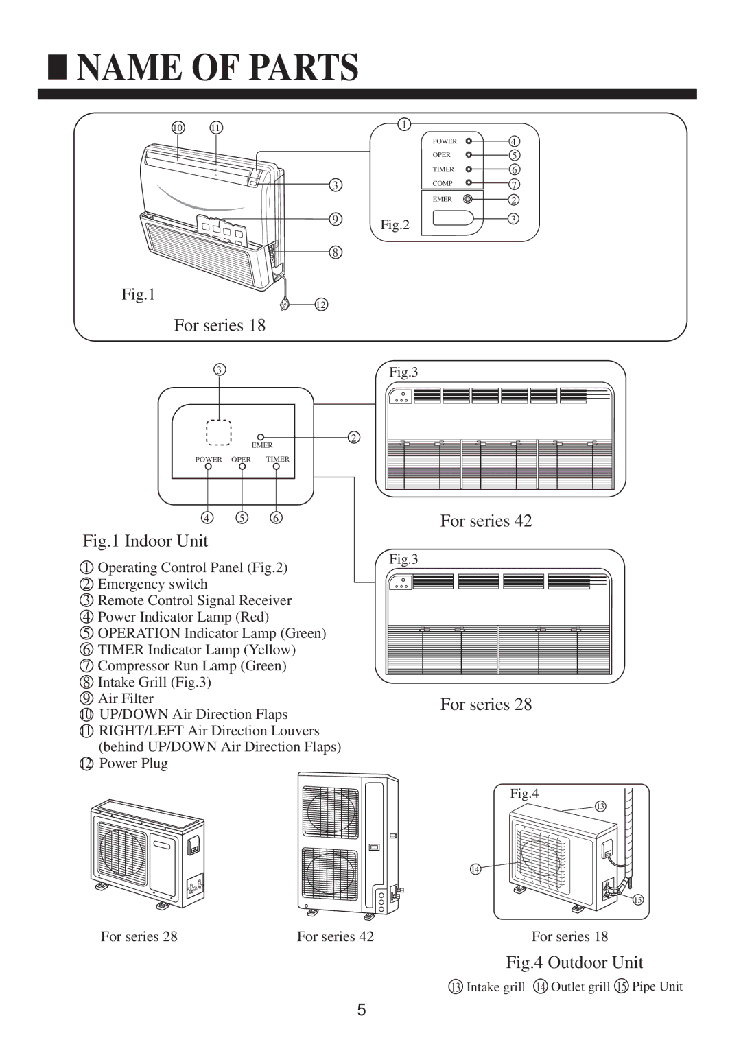
Fig.1 Indoor Unit
1Operating Control Panel (Fig.2)
2Emergency switch
3Remote Control Signal Receiver
4Power Indicator Lamp (Red)
5OPERATION Indicator Lamp (Green)
6TIMER Indicator Lamp (Yellow)
7Compressor Run Lamp (Green)
8Intake Grill (Fig.3)
9Air Filter
10UP/DOWN Air Direction Flaps
11RIGHT/LEFT Air Direction Louvers (behind UP/DOWN Air Direction Flaps)
12Power Plug
For series 42
Fig.3
For series 28
Fig.4
13
14
15
For series 28 | For series 42 | For series 18 |
Fig.4 Outdoor Unit
13 Intake grill 14 Outlet grill 15 Pipe Unit
5
