Introduction
Connection Options
® ®
|
|
| '\ / | ©L I |
|
|
|
|
|
|
|
| |
|
| © |
| DVl AUDIO |
|
|
|
|
|
|
|
| |
|
| fh |
|
|
|
|
|
| ,\ | j, |
|
|
|
|
| © |
|
|
| ® |
Y | Pb Pr | VGA AUDIO | VGA | i | ||
|
|
|
|
| © | |
| ||||||
|
|
|
|
| J |
|
©® | ® | @@ | @ | @ |
| |
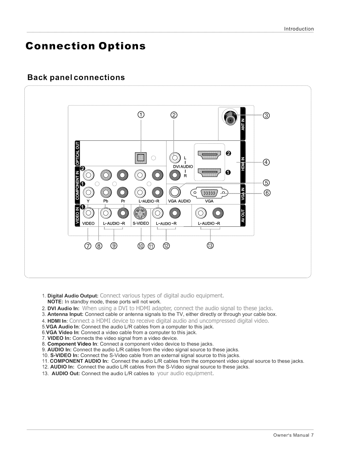
1. Digital Audio Output: Connect vat ous types ef d@tat asdo equipment
NOTE: In standby mode, these ports will not work.
2.DVi Audio In: Whet/ s '/(__/©Y:/to H©F_ _sdapter;connect the {_udo si{_n_sto these iacks
3.Antenna Input: Connect cable or antenna signals to the TV, either directly or through your cable box.
4.HDMI In: Co nect a HDf'41devce to receve dqbst udo and uncompressed dgta vdeo
5.VGA Audio In: Connect the audio L/R cables from a computer to this jack.
6.VGA Video In: Connect a video cable from a computer to this jack.
7.VIDEO In: Connects the video signal from a video device.
8.Component Video In: Connect a component video device to these jacks.
9.AUDIO In: Connect the audio L/R cables from the video signal source to these jacks.
10.
11.COMPONENT AUDIO In: Connect the audio L/R cables from the component video signal source to these jacks.
12.AUDIO In: Connect the audio L/R cables from the
13.AUDIO Out: Connect the audio L/R cables to your 8udo equ pmenL
Owner's Manual 7
