0010518181, HSU-12HG13-B, HSU-09HG13-B specifications
The Haier HSU-12HG13-B and HSU-09HG13-B are two advanced split air conditioning units designed to provide optimal cooling and heating solutions for residential and commercial spaces. Featuring cutting-edge technologies, these models ensure comfort and efficiency in various environments.The HSU-12HG13-B offers a cooling capacity of 12,000 BTU and is suitable for medium-sized rooms, while the HSU-09HG13-B, with a cooling capacity of 9,000 BTU, is perfect for smaller spaces. Both models boast energy efficiency through their EER (Energy Efficiency Ratio) ratings, assisting users in reducing energy consumption and lowering electricity bills without compromising on performance.
One of the standout features of both air conditioners is their inverter technology. This technology allows the units to adjust the compressor speed automatically, optimizing energy use and providing consistent temperature control. Inverter air conditioners are known for their quiet operation, making them suitable for bedrooms, study rooms, and other noise-sensitive areas.
Additionally, these models are equipped with a multi-functional remote control, allowing users to easily adjust settings from a distance. Features such as programmable timers, sleep mode, and temperature display enhance user convenience and comfort. The units also include a turbo mode for rapid cooling or heating, which is particularly beneficial during extreme weather conditions.
Both the HSU-12HG13-B and HSU-09HG13-B incorporate advanced air purification features. The integrated filters capture dust, allergens, and other airborne particles, ensuring cleaner and healthier air for occupants. The 0010518181 filter model is designed for easy maintenance, with accessible filters that can be cleaned or replaced without hassle.
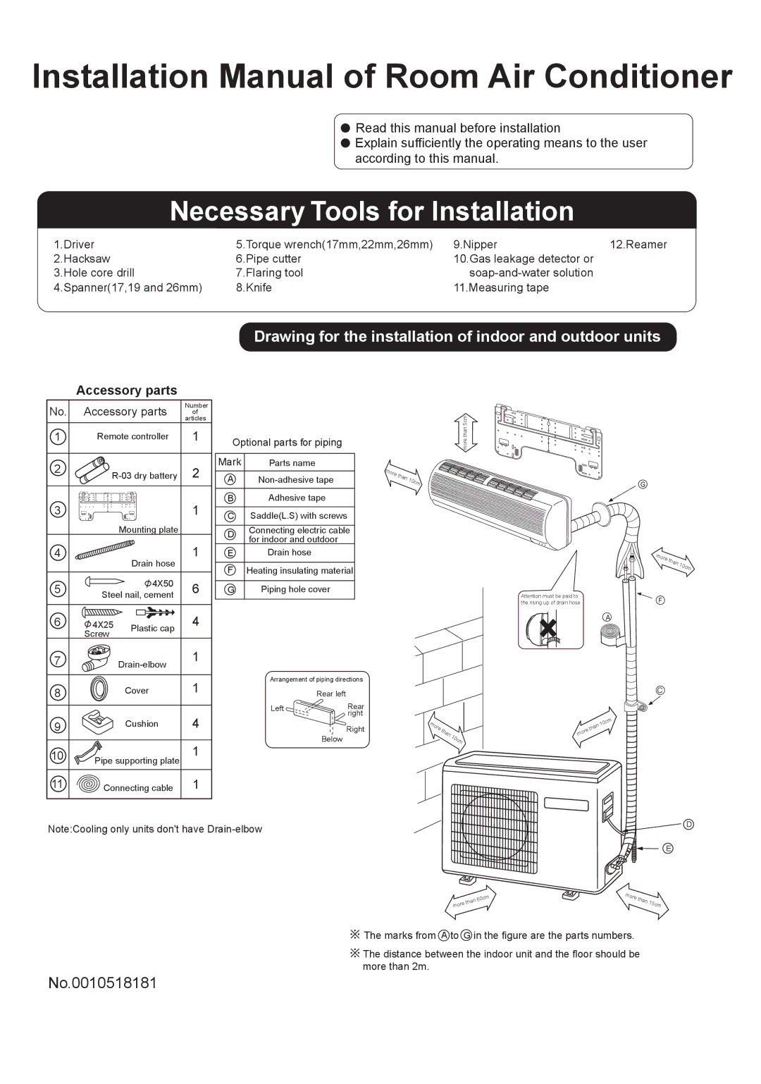
In terms of installation, these units come with a compact indoor unit design that fits seamlessly into modern interiors, and the outdoor unit is engineered for durability and quiet operation. They also adhere to international standards for performance and safety, giving users peace of mind in their purchase.
Overall, the Haier HSU-12HG13-B and HSU-09HG13-B air conditioning systems stand out for their efficiency, innovative technologies, and user-friendly features, making them excellent choices for anyone looking to enhance their indoor climate. With reliable performance and effective air purification, these models promise not only comfort but also healthier living spaces.