Manuals
/
Hampton Bay
/
Lawn and Garden
/
Outdoor Ceiling Fan
Hampton Bay
122 135
owner manual
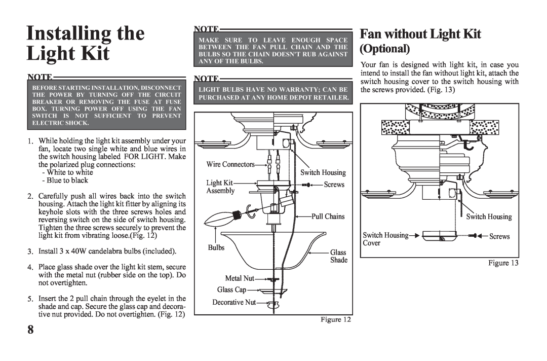
Installing the Light Kit, Fan without Light Kit, Optional
Models:
122 135
1
10
14
14
Download
14 pages
33.98 Kb
7
8
9
10
11
12
13
14
<
>
Troubleshooting
Specs
Install
Warranty
Page 10
Image 10
Page 9
Page 11
Page 10
Image 10
Page 9
Page 11
Contents
Hawkins
Ceiling Fan by Hampton Bay
Table of Contents
44” Hawkins
Date Purchased
Safety Rules - Read and Save These Instructions
Page
Tools Required
Installing Your Fan
Mounting Options
Hanging the Fan
Making the Electrical Connections
Ground
Finishing the Fan Installation
SUPPLY CIRCUIT
Conductor
Attaching the Fan Blades
Blade Balancing
Fan without Light Kit
Installing the Light Kit
Optional
Operating Your Fan
SOLUTION
Troubleshooting
PROBLEM
Care of Your Fan
SPEED
Specifications
FAN SIZE
VOLTS
Lifetime Limited Warranty
lifetime warranty on motor
Top
Page
Image
Contents