Installing the
Switch Box
CAUTION - To reduce the risk of electrical shock, disconnect the electrical supply circuit to the fan before installing the switch box.
1.Remove one serrated head screw from the black bracket below the fan motor assembly. Loosen, but do not remove the other two serrated head screws (Figure 12).
![]() Black
Black
Bracket
Switch Box Adaptor | Serrated Head |
| Screw(3) |
Figure 12
2.Align the key hole slots in the switch box adaptor with the two serrated head screws in the black bracket.
3.Turn the switch box adaptor clockwise until the two serrated head screws are situated in the narrow end of the keyholes.
4.
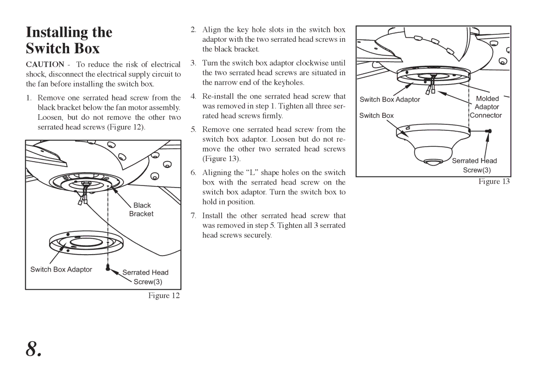
5.Remove one serrated head screw from the switch box adaptor. Loosen but do not re- move the other two serrated head screws (Figure 13).
6.Aligning the “L” shape holes on the switch box with the serrated head screw on the switch box adaptor. Turn the switch box to hold in position.
7.Install the other serrated head screw that was removed in step 5. Tighten all 3 serrated head screws securely.
Switch Box Adaptor | Molded |
| Adaptor |
Switch Box | Connector |
| Serrated Head |
| Screw(3) |
| Figure 13 |
8.