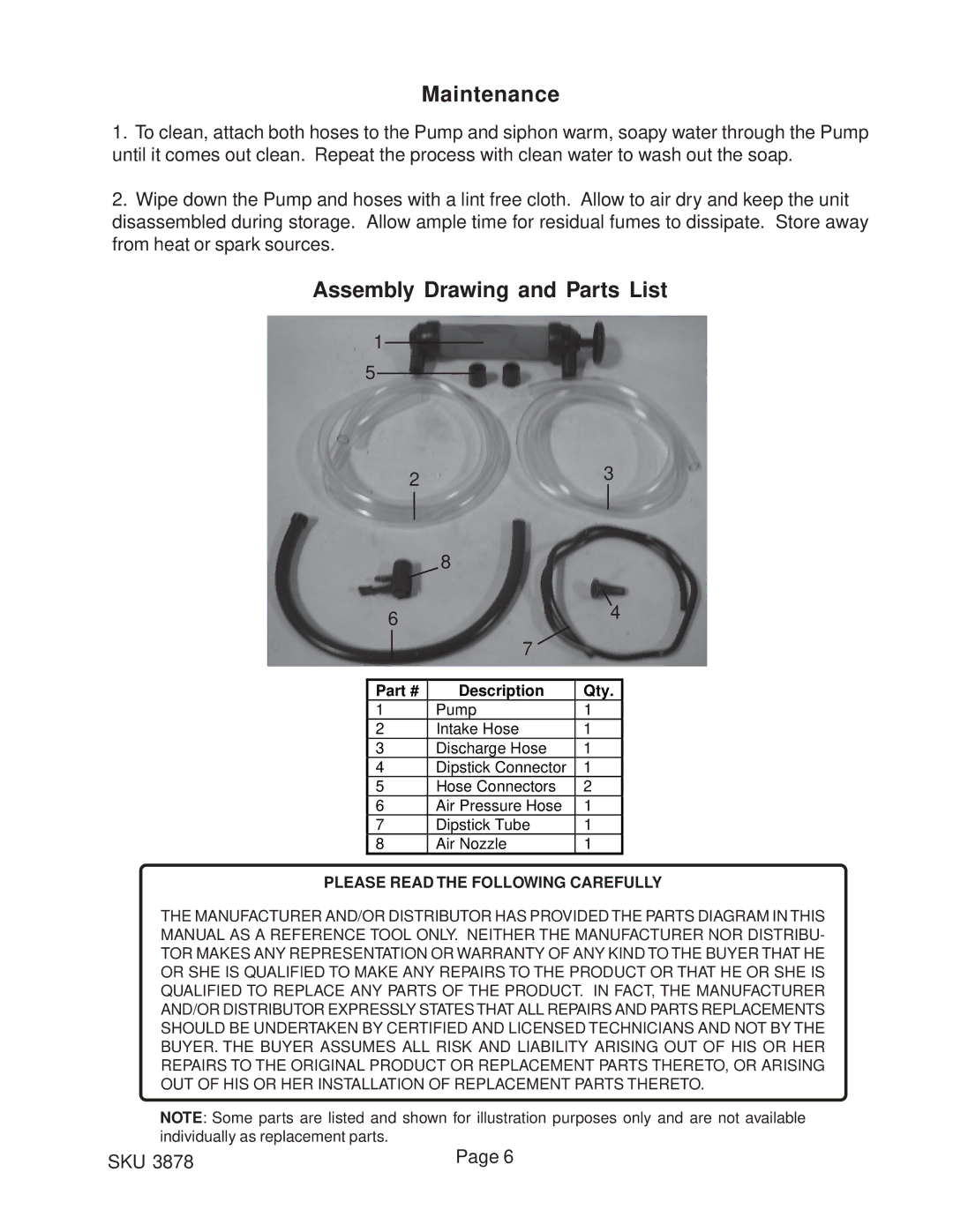
3878 specifications
Harbor Freight Tools is synonymous with affordable quality, and their 3878 model exemplifies this commitment to value. This versatile tool is designed for both professionals and DIY enthusiasts, offering an array of features that enhance its functionality in various applications.One of the standout features of the Harbor Freight Tools 3878 is its robust construction. Built to withstand rigorous use, it utilizes high-quality materials that ensure durability and longevity. This tool is often favored for its ability to perform reliably in demanding environments, making it ideal for both workshop and fieldwork scenarios.
The 3878 model is equipped with an innovative power system that maximizes efficiency. It boasts a powerful motor that delivers impressive torque, enabling users to tackle challenging tasks with ease. Whether you are drilling through tough materials or fastening components, the torque output of the 3878 ensures that the job gets done smoothly and quickly.
In addition to its power, this tool features an ergonomic design that enhances user comfort. The handle is thoughtfully crafted to provide a firm grip, reducing hand fatigue during extended use. This is particularly beneficial for professionals who spend long hours on the job, as it allows for greater precision and control.
Another significant characteristic of the Harbor Freight Tools 3878 is its versatility. This model comes with various attachments and accessories, expanding its usability across multiple tasks. From woodworking to automotive repair, the 3878 adapts to different applications effectively. This multifunctionality makes it a valuable addition to any toolbox.
Moreover, the user-friendly interface of the 3878 is a notable aspect that sets it apart. The intuitive controls simplify operation, allowing users to switch between functions seamlessly. This makes it accessible for beginners while still meeting the needs of seasoned professionals who require fast and efficient tool control.
Safety features are also prioritized in the design of the Harbor Freight Tools 3878. It is equipped with mechanisms that prevent accidental operation, ensuring that users can work with peace of mind. This emphasis on safety makes it a reliable choice for various work environments.
In conclusion, the Harbor Freight Tools 3878 is an exceptional tool that merges durability, efficiency, and versatility. With its powerful motor, ergonomic design, and innovative features, it stands out as an excellent option for those seeking a reliable companion for their projects. Whether you are a professional tradesperson or a home improvement novice, the 3878 is sure to meet your needs with its impressive capabilities.

