To Attach The Side Handle:
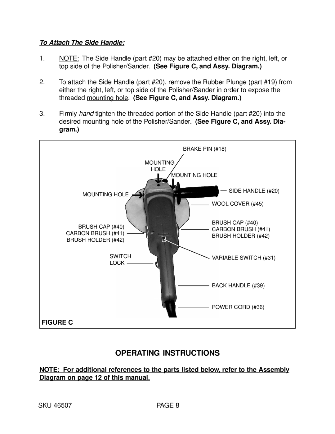
1.NOTE: The Side Handle (part #20) may be attached either on the right, left, or top side of the Polisher/Sander. (See Figure C, and Assy. Diagram.)
2.To attach the Side Handle (part #20), remove the Rubber Plunge (part #19) from either the right, left, or top side of the Polisher/Sander in order to expose the threaded mounting hole. (See Figure C, and Assy. Diagram.)
3.Firmly hand tighten the threaded portion of the Side Handle (part #20) into the desired mounting hole of the Polisher/Sander. (See Figure C, and Assy. Dia- gram.)
MOUNTING HOLE
BRUSH CAP (#40) CARBON BRUSH (#41) BRUSH HOLDER (#42)
SWITCH
LOCK
BRAKE PIN (#18)
MOUNTING
HOLE
MOUNTING HOLE
SIDE HANDLE (#20)
WOOL COVER (#45)
BRUSH CAP (#40)
CARBON BRUSH (#41)
BRUSH HOLDER (#42)
VARIABLE SWITCH (#31)
BACK HANDLE (#39)
POWER CORD (#36)
FIGURE C
OPERATING INSTRUCTIONS
NOTE: For additional references to the parts listed below, refer to the Assembly Diagram on page 12 of this manual.
SKU 46507 | PAGE 8 |
