
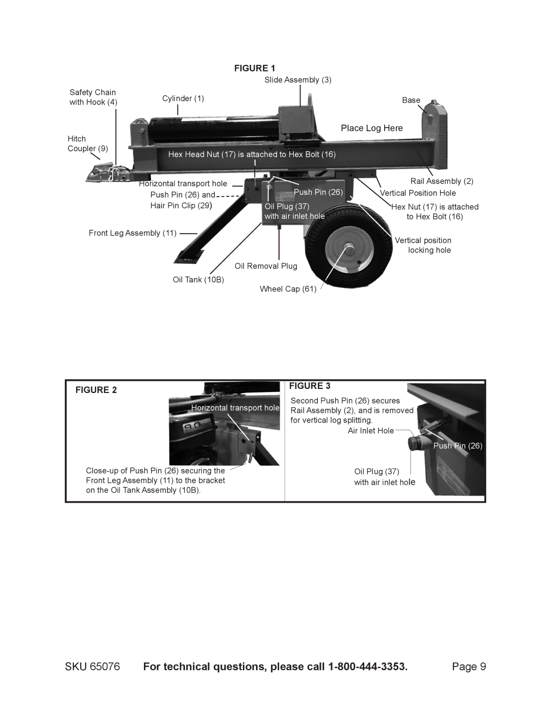
65076 specifications
Harbor Freight Tools has established a reputation for offering a wide range of affordable and useful tools, and one of their standout models is the 65076 electric hoist. This versatile piece of equipment is designed to make lifting heavy loads easier and more efficient, catering to both professional and DIY users. With its robust construction and thoughtful design, the 65076 has become a reliable choice for various applications in garages, workshops, and construction sites.One of the standout features of the Harbor Freight Tools 65076 is its powerful motor. This electric hoist can lift loads of up to 1,100 pounds, making it suitable for a variety of tasks, from lifting engines and machinery to hoisting heavy building materials. The motor operates with a smooth and consistent power delivery, ensuring that lifting heavy items is not only efficient but also safe.
The 65076 is equipped with a durable alloy steel frame and corrosion-resistant components, ensuring longevity and durability even in tough working conditions. The cable has a high tensile strength, reducing the risk of snapping under heavy loads. This attention to material selection ensures that users can rely on the hoist for repeated use without compromising safety.
Another essential aspect of the Harbor Freight 65076 is its user-friendly design. The hoist features a remote control, allowing users to operate the device from a safe distance. This feature is particularly useful in situations where the load obstructs the user’s view, enabling precise control throughout the lifting process. Additionally, it includes a built-in limit switch that automatically stops the hoist when the load reaches its maximum height, further enhancing safety.
The versatility of the 65076 makes it ideal for various applications. Whether lifting automotive parts, machinery, or other heavy objects, this hoist provides a straightforward solution that saves time and reduces physical strain on users. Thanks to its compact size, it can be mounted in small spaces, making it a practical choice for limited workshop environments.
In summary, the Harbor Freight Tools 65076 electric hoist is a powerful and durable lifting solution designed for both professional and home use. With its high lifting capacity, durable construction, user-friendly controls, and safety features, it stands out as an essential tool for anyone needing reliable hoisting capabilities. Whether for automotive repairs, construction work, or routine lifting tasks, the 65076 proves to be a valuable addition to any toolkit.