PLEASE READ THE FOLLOWING CAREFULLY
The manufacturer and/or distributor has provided the parts list and assembly diagram in this manual as a reference tool only. Neither the manufacturer or
distributor makes any representation or warranty of any kind to the buyer that
he or she is qualified to make any repairs to the product, or that he or she is qualified to replace any parts of the product. In fact, the manufacturer and/ or distributor expressly states that all repairs and parts replacements should be undertaken by certified and licensed technicians, and not by the buyer. The buyer assumes all risk and liability arising out of his or her repairs to the original product or replacement parts thereto, or arising out of his or her installation of replacement parts thereto.
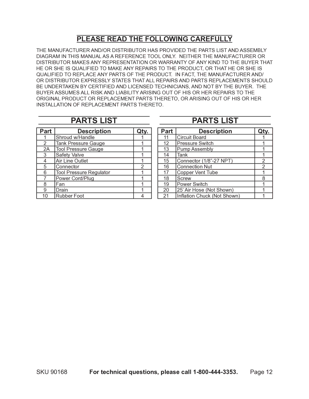
Parts List
Part | Description | Qty. |
1 | Shroud w/Handle | 1 |
2 | Tank Pressure Gauge | 1 |
2A | Tool Pressure Gauge | 1 |
3 | Safety Valve | 1 |
4 | Air Line Outlet | 1 |
5 | Connector | 2 |
6 | Tool Pressure Regulator | 1 |
7 | Power Cord/Plug | 1 |
8 | Fan | 1 |
9 | Drain | 1 |
10 | Rubber Foot | 4 |
Parts List
Part | Description | Qty. |
11 | Circuit Board | 1 |
12 | Pressure Switch | 1 |
13 | Pump Assembly | 1 |
14 | Tank | 1 |
15 | Connector | 2 |
16 | Connection Nut | 2 |
17 | Copper Vent Tube | 1 |
18 | Screw | 8 |
19 | Power Switch | 1 |
20 | 25’ Air Hose (Not Shown) | 1 |
21 | Inflation Chuck (Not Shown) | 1 |
SKU 90168 | For technical questions, please call | Page 12 |
