ASSEMBLY DIAGRAM
3
2
42
41
39
32 38 1 23
22
21
13
12 |
|
|
|
|
|
38 | 49 |
|
|
|
|
|
| 54 | 51 |
|
|
|
|
|
|
| |
|
|
|
|
| 43 |
45 |
|
| 53 |
| 11 |
|
|
| 52 50 |
|
|
|
|
|
|
| 40 |
16 |
| 17 | 14 |
|
|
|
|
|
| ||
|
|
|
|
| |
46 | 15 |
| 25 |
| 39 |
19 | 14 |
|
| ||
|
|
|
|
| |
20 |
| 18 | 34 |
| 38 |
|
|
| |||
| 6 | 33 32 | 35 | 36 | 37 |
| 31 |
| |||
|
|
| |||
| 29 |
|
|
|
|
30 | 28 | 39 |
|
| 2 |
| 5 |
|
| ||
24 |
| 41 |
|
| |
27 |
| 42 |
| ||
|
|
|
|
| |
26 |
|
|
|
|
|
25 |
|
| 34 |
|
|
|
| 48 |
| 40 | 1 |
|
|
|
|
| 55 |
8
9
21
22
7
10
49 12
3
47
46
44
45
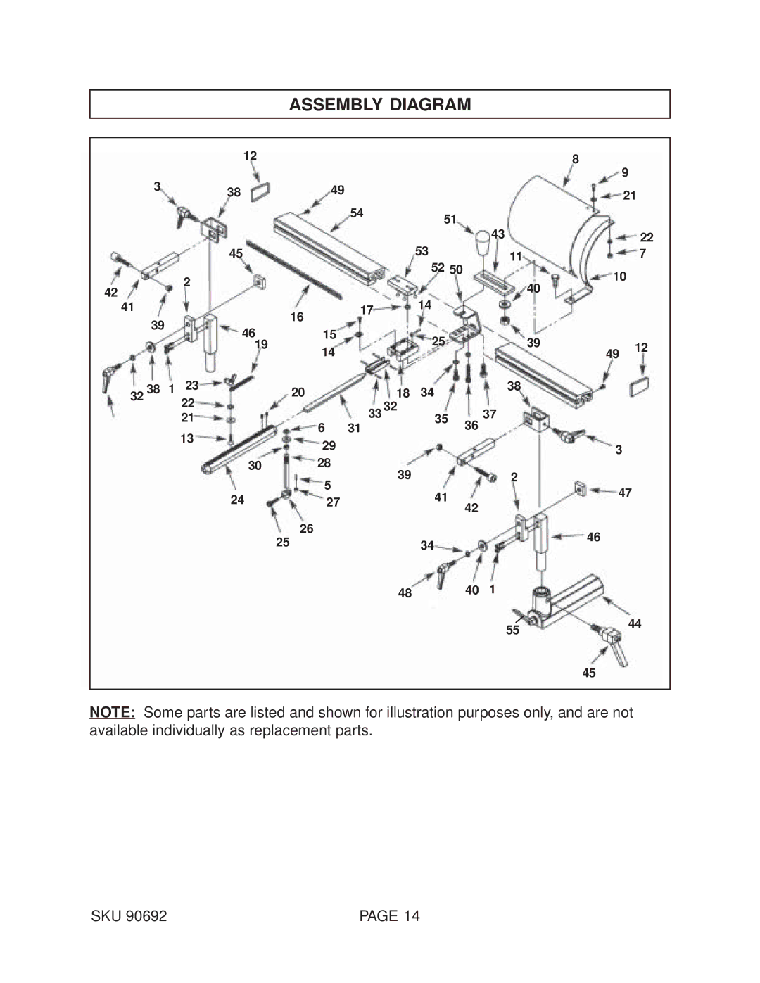
NOTE: Some parts are listed and shown for illustration purposes only, and are not available individually as replacement parts.
SKU 90692 | PAGE 14 |