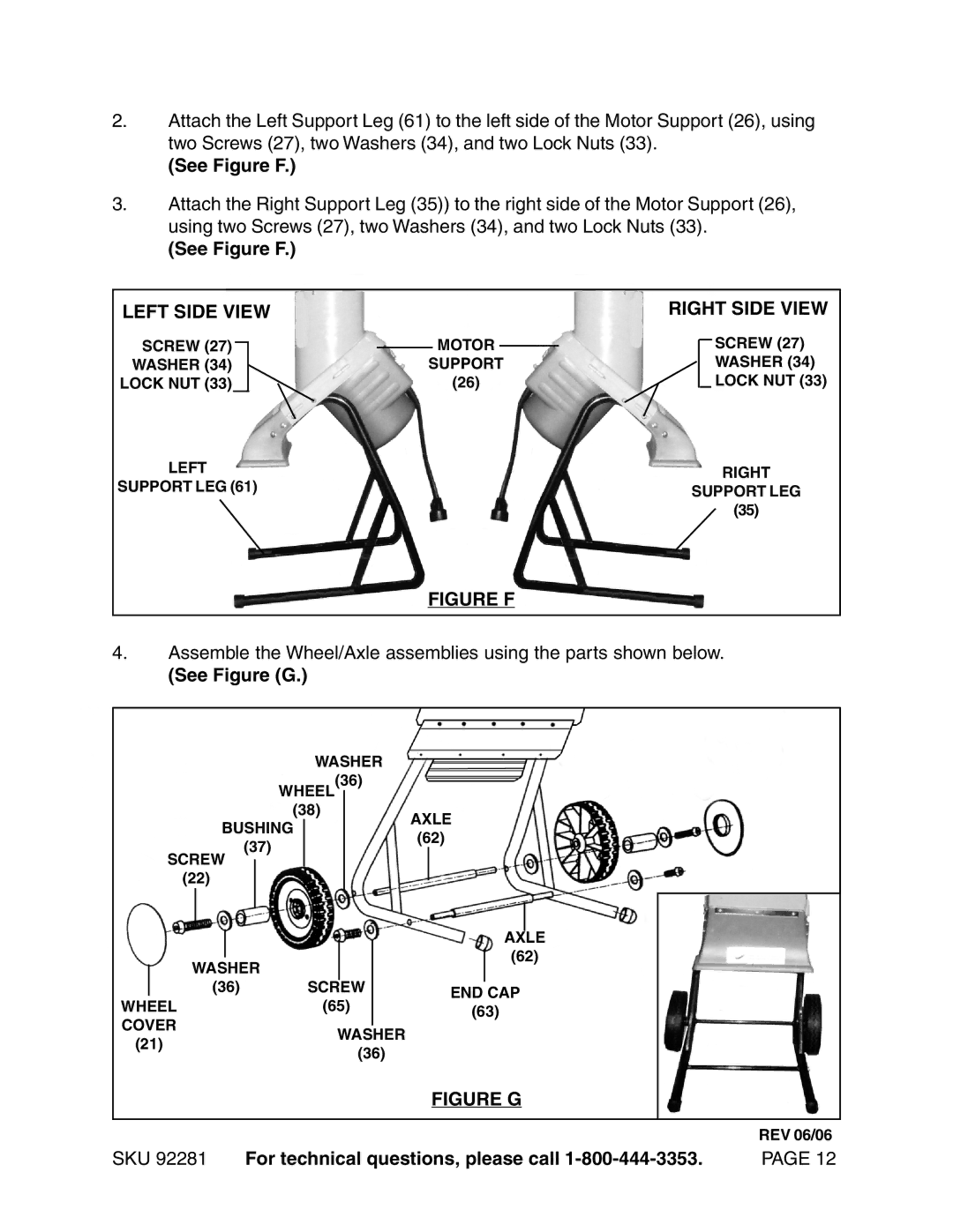
2.Attach the Left Support Leg (61) to the left side of the Motor Support (26), using two Screws (27), two Washers (34), and two Lock Nuts (33).
(See Figure F.)
3.Attach the Right Support Leg (35)) to the right side of the Motor Support (26), using two Screws (27), two Washers (34), and two Lock Nuts (33).
(See Figure F.)
LEFT SIDE VIEW |
|
|
| RIGHT SIDE VIEW |
SCREW (27) |
| MOTOR |
| SCREW (27) |
|
| |||
WASHER (34) | SUPPORT | WASHER (34) | ||
LOCK NUT (33) | (26) |
| LOCK NUT (33) | |
LEFT | RIGHT | |
SUPPORT LEG (61) | ||
SUPPORT LEG | ||
| ||
| (35) |
FIGURE F
4.Assemble the Wheel/Axle assemblies using the parts shown below.
(See Figure (G.)
WASHER
WHEEL(36) (38)
BUSHING
AXLE
(37)
SCREW
(22)
(62)
|
|
|
|
|
|
|
|
|
|
|
|
|
|
|
|
|
|
|
|
|
|
|
|
|
|
|
|
|
|
|
|
|
|
|
|
|
|
|
|
|
| AXLE | |
|
|
|
|
|
|
| ||||
|
|
|
|
|
|
|
|
| (62) | |
|
|
|
|
|
|
|
| |||
| WASHER |
|
|
| ||||||
|
|
|
|
|
|
|
| |||
| (36) | SCREW |
| END CAP | ||||||
WHEEL | (65) |
| ||||||||
| (63) |
| ||||||||
COVER |
|
|
|
| ||||||
|
|
|
|
|
|
| ||||
WASHER |
|
|
|
| ||||||
(21) |
|
|
|
|
|
| ||||
|
| (36) |
|
|
|
| ||||
|
|
|
|
|
|
|
| |||
|
|
|
|
|
|
| FIGURE G | |||
REV 06/06
SKU 92281 | For technical questions, please call | PAGE 12 |