|
|
|
|
|
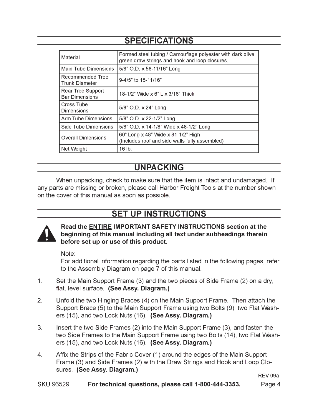
| Specifications | |
|
|
|
|
| Material | Formed steel tubing / Camouflage polyester with dark olive |
|
| green draw strings and hook and loop closures. |
| |
|
|
| |
| Main Tube Dimensions | 5/8” O.D. x |
|
|
|
|
|
| Recommended Tree |
| |
| Trunk Diameter |
| |
|
|
| |
| Rear Tree Support |
| |
| Bar Dimensions |
| |
|
|
| |
| Cross Tube | 5/8” O.D. x 24” Long |
|
| Dimensions |
| |
|
|
| |
| Arm Tube Dimensions | 5/8” O.D. x |
|
| Side Tube Dimensions | 5/8” O.D. x |
|
| Overall Dimensions | 60” Long x 48” Wide x |
|
| (Includes roof and side walls fully assembled) |
| |
|
|
| |
| Net Weight | 16 lb. |
|
Unpacking
When unpacking, check to make sure that the item is intact and undamaged. If any parts are missing or broken, please call Harbor Freight Tools at the number shown on the cover of this manual as soon as possible.
Set Up Instructions
Read the entire Important Safety Instructions section at the beginning of this manual including all text under subheadings therein before set up or use of this product.
Note:
For additional information regarding the parts listed in the following pages, refer to the Assembly Diagram on page 7 of this manual.
1.Set the Main Support Frame (3) and the two pieces of Side Frame (2) on a dry, flat, level surface. (See Assy. Diagram.)
2.Unfold the two Hinging Braces (4) on the Main Support Frame. Then attach the Support Brace (5) to the Main Support Frame using two Bolts (9), two Flat Wash- ers (15), and two Lock Nuts (16). (See Assy. Diagram.)
3.Insert the two Side Frames (2) into the Main Support Frame (3), and fasten the two Side Frames to the Main Support Frame using two Bolts (14), two Flat Wash- ers (15), and two Lock Nuts (16). (See Assy. Diagram.)
4.Affix the Strips of the Fabric Cover (1) around the edges of the Main Support
Frame (3) and Side Frames (2) with the Draw Strings and Hook and Loop Clo- sures. (See Assy. Diagram.)
REV 09a
SKU 96529 | For technical questions, please call | Page 4 |
