Parts List and Diagram |
|
| |||
|
|
|
|
| |
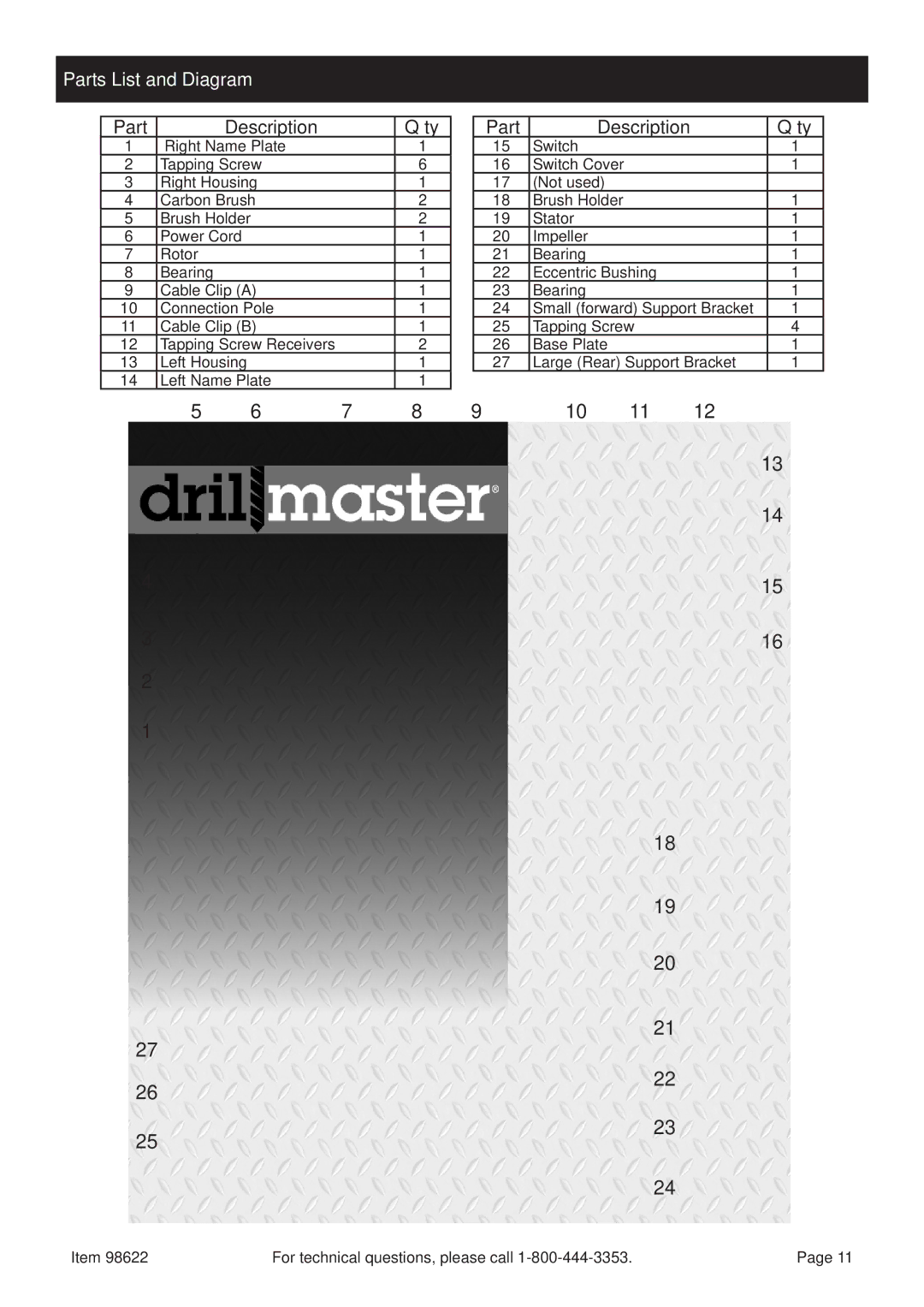
| Part | Description |
| Q’ty | |
| 1 | Right Name Plate |
| 1 | |
| 2 | Tapping Screw |
| 6 | |
| 3 | Right Housing |
| 1 | |
| 4 | Carbon Brush |
| 2 | |
| 5 | Brush Holder |
| 2 | |
| 6 | Power Cord |
|
| 1 |
| 7 | Rotor |
|
| 1 |
| 8 | Bearing |
|
| 1 |
| 9 | Cable Clip (A) |
| 1 | |
| 10 | Connection Pole |
| 1 | |
| 11 | Cable Clip (B) |
| 1 | |
| 12 | Tapping Screw Receivers |
| 2 | |
| 13 | Left Housing |
|
| 1 |
| 14 | Left Name Plate |
| 1 | |
|
| 5 | 6 | 7 | 8 |
4
3
2
1
27
26
25
| Part | Description | Q’ty | ||
| 15 | Switch |
|
| 1 |
| 16 | Switch Cover |
|
| 1 |
| 17 | (Not used) |
|
|
|
| 18 | Brush Holder |
|
| 1 |
| 19 | Stator |
|
| 1 |
| 20 | Impeller |
|
| 1 |
| 21 | Bearing |
|
| 1 |
| 22 | Eccentric Bushing |
| 1 | |
| 23 | Bearing |
|
| 1 |
| 24 | Small (forward) Support Bracket | 1 | ||
| 25 | Tapping Screw |
| 4 | |
| 26 | Base Plate |
|
| 1 |
| 27 | Large (Rear) Support Bracket | 1 | ||
9 | 10 | 11 | 12 |
| |
13
14
15
16
18
19
20
21
22
23
24
Safety
Setup
Operation
Maintenance
Item 98622 | For technical questions, please call | Page 11 |