Introduction
Thank you for choosing this Harman Kardon® product. With your purchase of a new AB 2 Amplified
Always observe the appropriate safety codes for concealed wiring. Be extremely careful not to cut through or drill into concealed wiring or pipes. Make a small inspection opening before cutting or drilling.
Dust or dirt can cause special problems on wiring contacts. Be sure all contacts are clean, and that all parts are installed correctly to protect them from dust and dirt.
Your Harman Kardon AB 2 Amplified
What Is Included
•Two
•Remote control
You are responsible for providing a
You must also provide the speakers and a sufficient length of Category 5/5e (or better) UTP (unshielded twisted pair) cable and an
Press and hold this button to select The Bridge/DMP as the multiroom source. If a compatible iPod (not included) is docked in The Bridge, it will begin playing. The Bridge is a Harman Kardon accessory that is sold separately. It may be connected to a The
CD Source Control – When the AB 2 is used with a Harman Kardon ABH 4000 or other compatible multizone
Installation and Connection
offer control over source selection and operation, local volume and system power.
To fully enjoy the benefits of remote keypad control, please take a few minutes to read this owner’s manual. It contains important information that will guide you through the correct and safe installation of your Amplified
If you have any questions about this product, its installation or its operation, please contact your retailer or custom installer. They are your best source of product information.
Features
■ Simple connection to any |
product or ABH series hub |
The AB 2 is only to be installed by qualified personnel and as per the requirements of all applicable state and local building codes, as well as NEC requirements. Check with your local authorities as needed to ensure that all wiring inside walls is installed in compliance with the proper standards. Failure to do so may present a potential safety hazard.
If you have any doubt about your ability to work with electrical and telecommunications wiring, you are advised to hire a licensed electrician or custom installer to install this product.
Installation Planning
The AB 2 may be installed in any location appropriate for standard
AB 2 before installation.
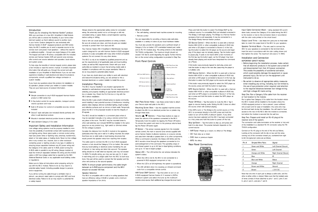
Front-Panel Controls
AVR Tuner/DMP Control
CD Source Control
DVD Source Control
MP3 Source Control
Power Off/Mute
Skip Up/Down
Volume Up/Down
IR Sensor
Status LED
Mounting Screw Slot
already been playing and would have interpreted the command as a Pause.
If this button was previously tapped to start play, press and hold the button to skip to the next disc (assuming the player is a multidisc unit).
DVD Source Control – When the AB 2 is used with a Harman Kardon ABH 4000 or other compatible multizone
If this button was previously tapped to select the DVD player as the source, press and hold the button to begin play.
MP3 Source Control – When the AB 2 is used with a Harman Kardon ABH 4000 or other compatible multizone
IMPORTANT SAFETY NOTES:
•Before beginning the installation process, make certain that all electronic products in the system are turned off and disconnected from their A/V power connection.
This avoids the possibility of accidental activation, which could possibly damage the equipment or cause personal injury. Do not turn on the equipment until instructed to do so.
•Be certain to observe all appropriate safety measures when installing any wiring, including, but not limited to, the use of eye protection when required, and attention to the required distances between
Step One: Run a Category 5/5e cable from the receiver or hub location to the module.
■ |
volume up/down and mute |
■ |
included |
■ |
other |
■ Mounts in standard electrical junction boxes or plaster rings |
■ Uses standard Category 5/5e cable |
Important Safety and Installation Information
Make sure to follow all instructions when preparing wiring for use with the AB 2 module. Failure to do so may result in a potential safety hazard, including possible danger to persons and/or equipment.
If you will be running the cable through a ventilation riser or plenum, use
Since the AB 2 uses a
The AB 2 should be installed in a convenient place where it may be operated manually, or by using a remote control from any place in the room. The AB 2 may be mounted close to other wall switches, but it should NEVER be installed in the same gang box as any product (e.g., light switch or dimmer) where AC line voltage is present.
Consider the distance from the AB 2 module to the speakers, particularly when they are
The cable used to connect the AB 2 to the
NOTE: To ensure proper performance, the cable length between an
Speaker Selection
The AB 2 is compatible with
Mounting Screw Slots – Use the supplied machine screws to attach the AB 2 to an electrical junction box or plaster ring through these slots.
Volume ⁄/ ¤ Buttons – Press these buttons to raise or lower the volume of the speakers connected to the AB 2. Temporarily mute the system by tapping the Power Off button. To unmute the system and return to the previous volume level, tap the Power Off button again.
IR Sensor – This sensor receives signals from the included remote control, the main or
Status LED – The LED behind the red window indicates the system’s status.
•When the LED is not lit, the AB 2 is not connected to a powered
•When the LED is at full brightness, the system is operational.
•The LED will blink when it is receiving an infrared command code from a compatible remote control.
AVR Tuner/DMP Control – Tap this button to turn on an
the source.
Power Off/Mute – Tap this button to mute the AB 2. Tap it again to resume hearing audio. Muting the AB 2 does not affect the source, which will continue playing.
If the AVR’s tuner or The Bridge is the current source, or if the AB 2 is connected directly to the AVR, press and hold this button to turn off the AVR’s multiroom system. If any other source has been selected and the AB 2 has been connected to a hub, press and hold this button to power off the hub.
Skip Up/Down – Tap this button to skip up, and press and hold it to skip down. The precise behavior depends on the current source:
•AVR Tuner: Preset up or down; no effect on The Bridge
•CD: Track skip up or down
•DVD: Next or previous chapter
•MP3: No effect
Rear-Panel Connections
Connection Block
Run a
Step Two: Prepare and install an
The connection and cable termination at the receiver or hub end of the installation is a standard
Connect an
Pin # | Striped Wire Pairs | Signal |
1 | Green and White | Left Channel Ground |
|
|
|
2 | Green | Left Channel |
|
|
|
3 | Orange and White | Right Channel Ground |
|
|
|
4 | Blue | IR |
|
|
|
5 | Blue and White | Status |
|
|
|
6 | Orange | Right Channel |
7 | Brown and White | Ground |
|
|
|
8 | Brown | +24V DC |
Note that one wire in each pair is always a solid color, and the other is either white or striped. Make sure that the twisted pairs of wires consist of those attached to pins 1 and 2, pins 3 and 6, pins 4 and 5, and pins 7 and 8.