13
Top Landing Gate (optional)
The optional top landing gate is provided with a combination mechanical lock and electric contact (interlock).
The interlock:
•Prevents the lift from running if the gate is not closed.
•Prevents the gate from being opened if the platform is not at the top landing.
•Unlocks when the lift is on the upper limit switch.
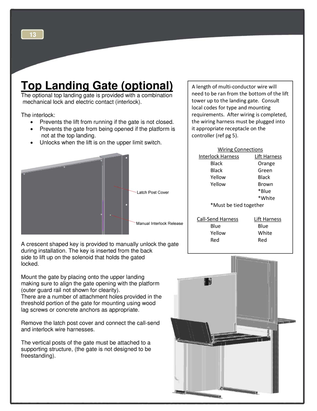
A crescent shaped key is provided to manually unlock the gate during installation. The key is inserted from the back
side to lift up on the solenoid that holds the gated locked.
Mount the gate by placing onto the upper landing making sure to align the gate opening with the platform (outer guard rail not shown for clearity).
There are a number of attachment holes provided in the threshold portion of the gate for mounting using wood lag screws or concrete anchors as appropriate.
Remove the latch post cover and connect the
The vertical posts of the gate must be attached to a supporting structure, (the gate is not designed to be freestanding).
Alength of multi‐conductor wire will need to be ran from the bottom of the lift tower up to the landing gate. Consult local codes for type and mounting requirements. After wiring is completed, the wiring harness must be plugged into it appropriate receptacle on the controller (ref pg 5).
Wiring Connections
Interlock Harness | Lift Harness |
Black | Orange |
Black | Green |
Yellow | Black |
Yellow | Brown |
| *Blue |
| *White |
*Must be tied together | |
Call‐Send Harness | Lift Harness |
Blue | Blue |
Yellow | White |
Red | Red |