
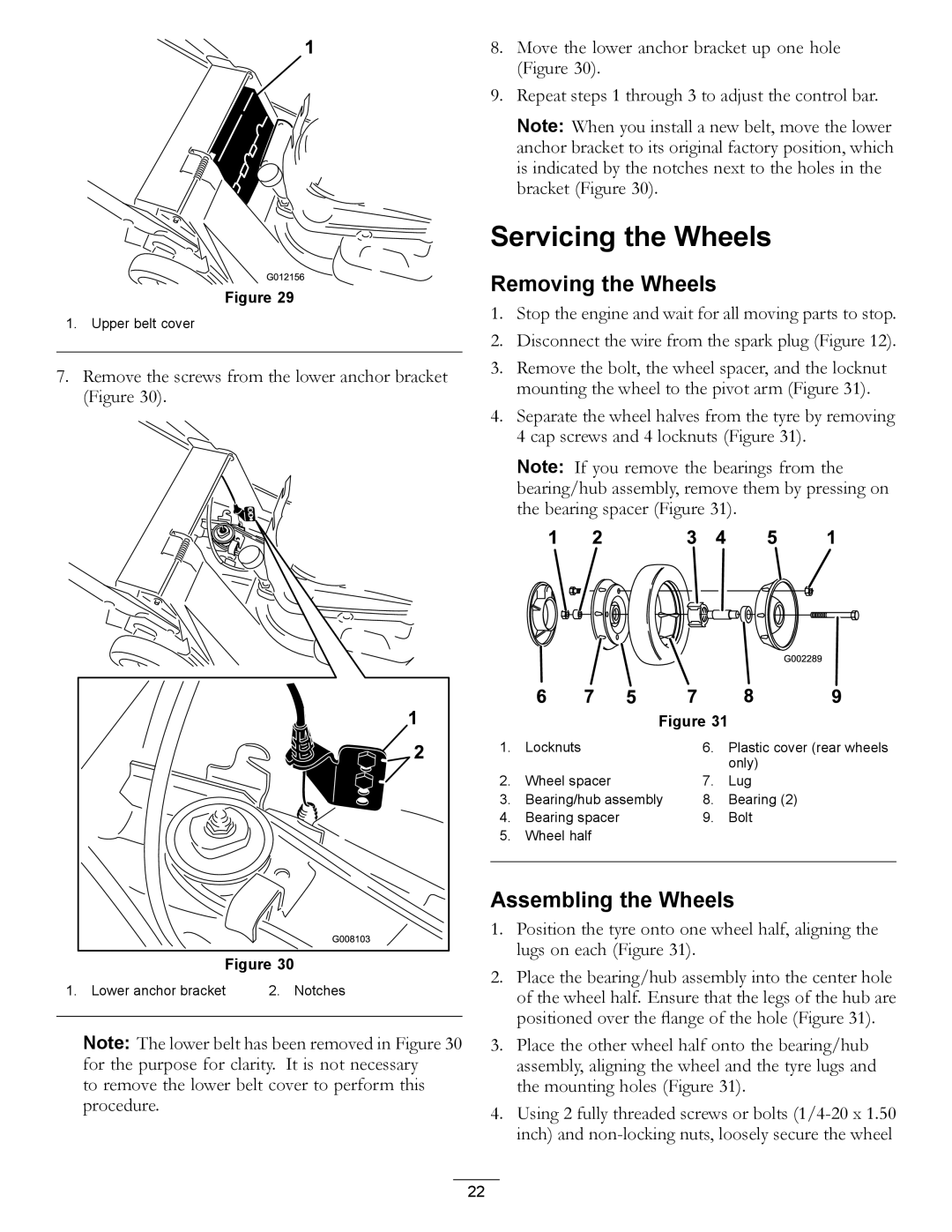
455E specifications
The Hayter Mowers 455E is a standout choice for homeowners and garden enthusiasts seeking a reliable and efficient lawn mower. This robust machine is designed for high performance, making lawn care easy and enjoyable. With a passion for quality and craftsmanship, Hayter continues to build on its reputation for creating exceptional gardens and outdoor spaces.One of the main features of the 455E is its 4-in-1 functionality, offering the capability to mow, mulch, side discharge, and collect grass clippings. This versatility allows users to tailor their mowing experience based on lawn conditions and personal preferences. The mower’s 53 cm cutting width is perfect for medium to large lawns, enabling a quicker and more efficient mowing process.
The 455E is powered by Hayter’s innovative electric start system. Unlike traditional mowers, which require pulling a cord to start, the electric start technology simplifies the process with the push of a button. This feature is especially beneficial for those who may find manual starting challenging. The mower is equipped with a powerful 158cc Loncin engine that delivers reliable performance and excellent fuel efficiency, allowing for longer mowing sessions without frequent refueling.
Additionally, the Hayter Mowers 455E features a fully adjustable cutting height, ranging from 25mm to 70mm. This allows users to achieve their desired grass length and maintain a healthy lawn throughout the seasons. The mower also boasts a robust steel deck construction, ensuring durability and stability during use. The quality of the materials used in its manufacture underlines Hayter’s commitment to providing long-lasting, dependable garden solutions.
Comfort is another focus of the 455E design. With an ergonomic handle that can be adjusted to different heights, users can mow their lawns without unnecessary strain. The foldable handles further add to the product's convenience, making storage easy and efficient.
In summary, the Hayter Mowers 455E combines advanced technology, versatility, and user-centric features to deliver an outstanding lawn care experience. Its 4-in-1 capabilities, electric start, powerful engine, adjustable cutting heights, and comfortable design make it a top choice for anyone looking to keep their lawn in pristine condition. With the 455E, maintaining a beautiful garden has never been easier.