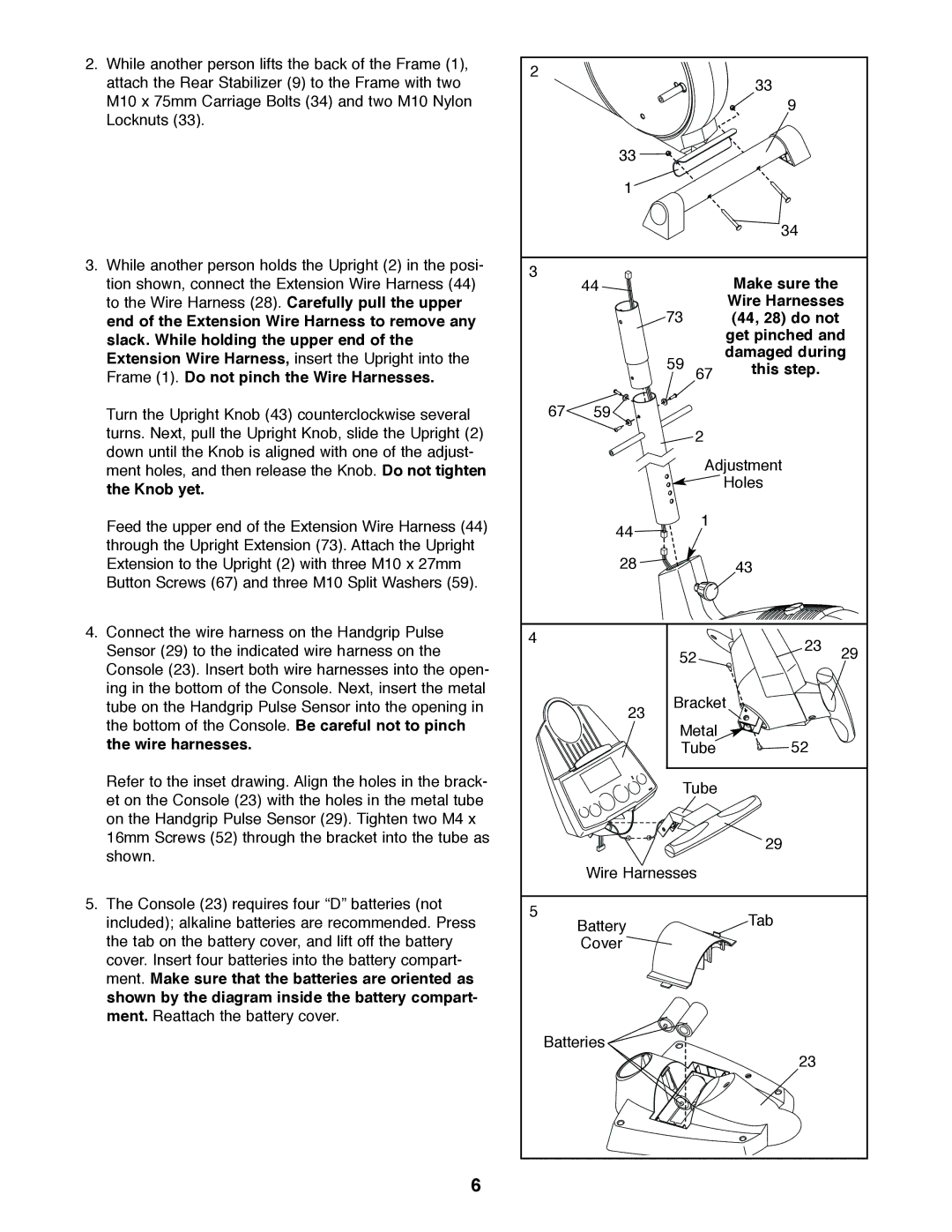
2.While another person lifts the back of the Frame (1), attach the Rear Stabilizer (9) to the Frame with two M10 x 75mm Carriage Bolts (34) and two M10 Nylon Locknuts (33).
3.While another person holds the Upright (2) in the posi- tion shown, connect the Extension Wire Harness (44) to the Wire Harness (28). Carefully pull the upper end of the Extension Wire Harness to remove any slack. While holding the upper end of the Extension Wire Harness, insert the Upright into the Frame (1). Do not pinch the Wire Harnesses.
Turn the Upright Knob (43) counterclockwise several turns. Next, pull the Upright Knob, slide the Upright (2) down until the Knob is aligned with one of the adjust- ment holes, and then release the Knob. Do not tighten the Knob yet.
Feed the upper end of the Extension Wire Harness (44) through the Upright Extension (73). Attach the Upright Extension to the Upright (2) with three M10 x 27mm Button Screws (67) and three M10 Split Washers (59).
4.Connect the wire harness on the Handgrip Pulse Sensor (29) to the indicated wire harness on the Console (23). Insert both wire harnesses into the open- ing in the bottom of the Console. Next, insert the metal tube on the Handgrip Pulse Sensor into the opening in the bottom of the Console. Be careful not to pinch the wire harnesses.
Refer to the inset drawing. Align the holes in the brack- et on the Console (23) with the holes in the metal tube on the Handgrip Pulse Sensor (29). Tighten two M4 x 16mm Screws (52) through the bracket into the tube as shown.
5.The Console (23) requires four “D” batteries (not included); alkaline batteries are recommended. Press the tab on the battery cover, and lift off the battery cover. Insert four batteries into the battery compart- ment. Make sure that the batteries are oriented as shown by the diagram inside the battery compart- ment. Reattach the battery cover.
2 |
|
|
| 33 |
|
|
|
|
|
| |
|
|
|
| 9 |
|
| 33 |
|
|
|
|
| 1 |
|
|
|
|
|
|
|
| 34 |
|
3 | 44 |
|
| Make sure the |
|
|
|
|
| ||
|
| 73 |
| Wire Harnesses | |
|
|
| (44, 28) do not |
| |
|
|
|
| get pinched and | |
|
| 59 |
| damaged during | |
|
| 67 | this step. |
| |
|
|
|
| ||
|
|
|
|
| |
67 | 59 |
|
|
|
|
|
|
| 2 |
|
|
|
|
| Adjustment |
| |
|
|
|
| Holes |
|
| 44 |
| 1 |
|
|
|
|
|
|
| |
| 28 |
|
| 43 |
|
4 |
|
|
| 23 | 29 |
|
| 52 | |||
|
|
| |||
| 23 | Bracket |
| ||
|
|
|
|
| |
|
| Metal | 52 |
| |
|
| Tube |
| ||
|
| Tube |
|
| |
|
|
|
| 29 |
|
| Wire Harnesses |
|
| ||
5 | Battery |
|
| Tab |
|
|
|
|
| ||
|
|
|
|
| |
| Cover |
|
|
|
|
Batteries |
|
|
|
| |
|
|
|
| 23 |
|
6
