ASSEMBLY
To hire an authorized service technician to assemble the treadmill, call
Assembly requires two persons. Set the treadmill in a cleared area and remove all packing materials. Do not dispose of the packing materials until assembly is completed. Note: The underside of the treadmill walking belt is coated with
Assembly requires the included hex key | and your own phillips screwdriver | (with a |
shaft at least 6" long) wire cutters | , and an adjustable wrench | . |
Use the drawings below to identify the hardware used during assembly. Note: If a part is not in the parts bag, check to see if it has been preattached to one of the parts to be assembled. To avoid damaging plastic parts, do not use power tools for assembly.
3/4” Screw | Ground Screw | Screw | |
| Upper Latch Shock Bolt | ||
|
| ||
|
|
| |
Extension Leg Nut |
| Lower Latch Shock Bolt | |
|
|
| Nut |
|
|
| Extension Leg Bolt |
Star Washer |
|
|
|
|
|
| Handrail Bolt |
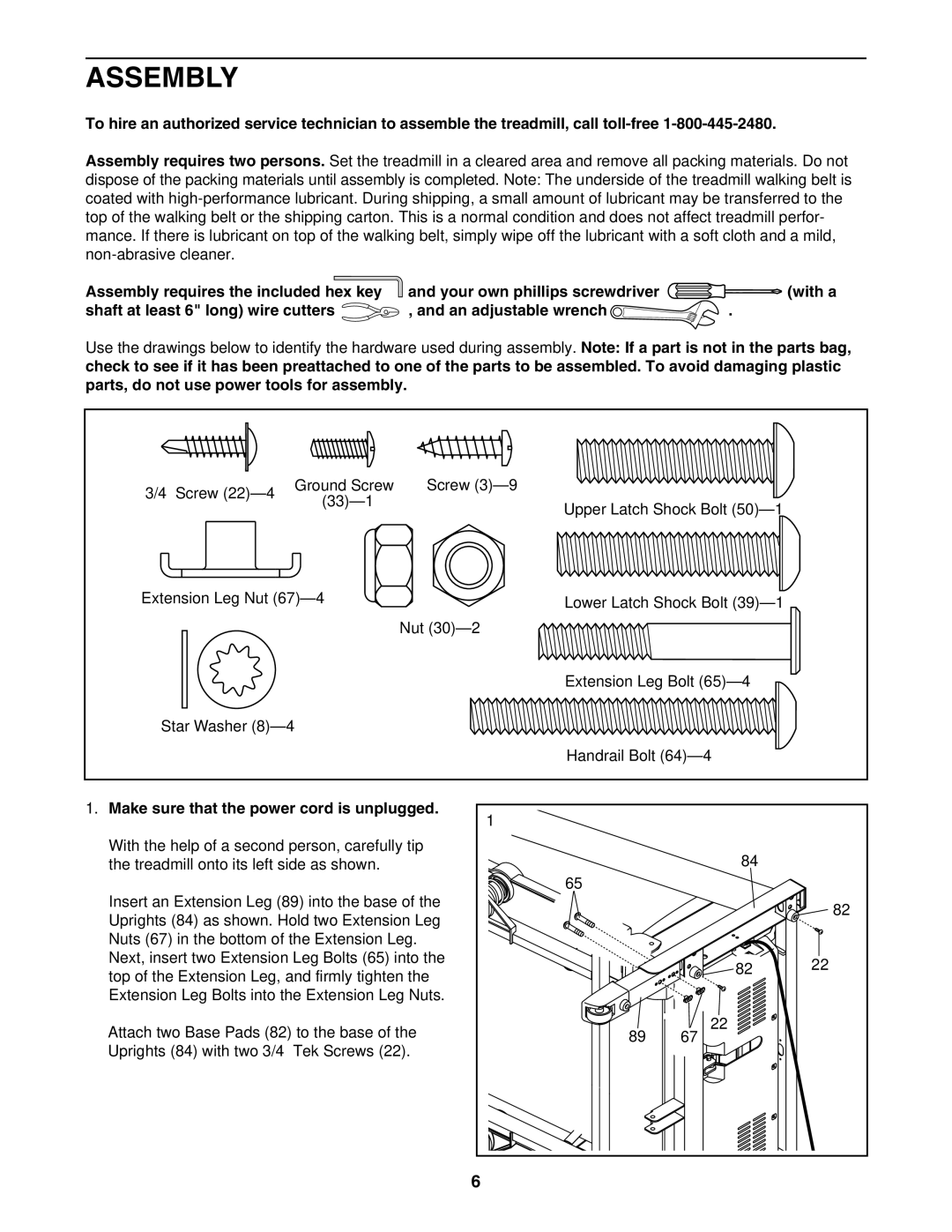
1. Make sure that the power cord is unplugged. | 1 |
|
|
|
|
| |
With the help of a second person, carefully tip |
| 84 |
|
the treadmill onto its left side as shown. |
|
| |
| 65 |
|
|
Insert an Extension Leg (89) into the base of the |
|
| 82 |
Uprights (84) as shown. Hold two Extension Leg |
|
| |
|
|
| |
Nuts (67) in the bottom of the Extension Leg. |
|
|
|
Next, insert two Extension Leg Bolts (65) into the |
| 82 | 22 |
top of the Extension Leg, and firmly tighten the |
| ||
|
|
| |
Extension Leg Bolts into the Extension Leg Nuts. |
|
|
|
Attach two Base Pads (82) to the base of the | 89 | 22 |
|
67 |
| ||
Uprights (84) with two 3/4” Tek Screws (22). |
|
|
|
| 6 |
|
|