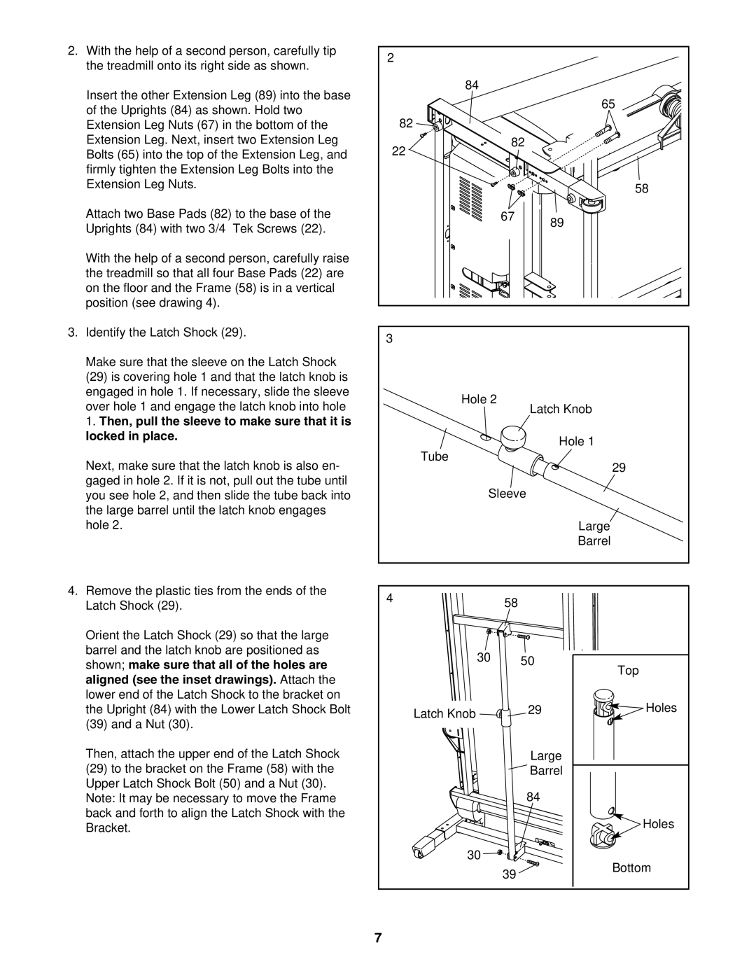
2. With the help of a second person, carefully tip | 2 |
|
|
|
|
the treadmill onto its right side as shown. |
|
|
|
| |
|
|
|
|
| |
Insert the other Extension Leg (89) into the base |
| 84 |
|
|
|
|
|
| 65 | ||
of the Uprights (84) as shown. Hold two |
|
|
| ||
82 |
|
|
|
| |
Extension Leg Nuts (67) in the bottom of the |
|
|
|
| |
Extension Leg. Next, insert two Extension Leg | 22 |
| 82 |
|
|
Bolts (65) into the top of the Extension Leg, and |
|
|
|
| |
firmly tighten the Extension Leg Bolts into the |
|
|
|
|
|
Extension Leg Nuts. |
|
|
|
| 58 |
|
|
|
|
| |
Attach two Base Pads (82) to the base of the |
|
| 67 | 89 |
|
Uprights (84) with two 3/4” Tek Screws (22). |
|
|
|
| |
|
|
|
|
| |
With the help of a second person, carefully raise |
|
|
|
|
|
the treadmill so that all four Base Pads (22) are |
|
|
|
|
|
on the floor and the Frame (58) is in a vertical |
|
|
|
|
|
position (see drawing 4). |
|
|
|
|
|
3. Identify the Latch Shock (29). | 3 |
|
|
|
|
|
|
|
|
| |
Make sure that the sleeve on the Latch Shock |
|
|
|
|
|
(29) is covering hole 1 and that the latch knob is |
|
|
|
|
|
engaged in hole 1. If necessary, slide the sleeve |
| Hole 2 |
|
|
|
over hole 1 and engage the latch knob into hole |
|
| Latch Knob |
| |
|
|
|
| ||
1. Then, pull the sleeve to make sure that it is |
|
|
|
|
|
locked in place. |
|
|
| Hole 1 |
|
|
|
|
|
| |
Next, make sure that the latch knob is also en- |
| Tube |
|
| 29 |
|
|
|
| ||
gaged in hole 2. If it is not, pull out the tube until |
| Sleeve |
|
| |
you see hole 2, and then slide the tube back into |
|
|
| ||
the large barrel until the latch knob engages |
|
|
|
|
|
hole 2. |
|
|
| Large |
|
|
|
|
| Barrel |
|
4. Remove the plastic ties from the ends of the | 4 |
| 58 |
|
|
Latch Shock (29). |
|
|
| ||
|
|
|
| ||
Orient the Latch Shock (29) so that the large |
|
|
|
|
|
barrel and the latch knob are positioned as |
| 30 | 50 |
| |
shown; make sure that all of the holes are |
| Top | |||
|
| ||||
aligned (see the inset drawings). Attach the |
|
|
|
| |
|
|
|
|
| |
lower end of the Latch Shock to the bracket on |
|
|
|
| Holes |
the Upright (84) with the Lower Latch Shock Bolt |
| Latch Knob |
| 29 | |
(39) and a Nut (30). |
|
|
|
| |
|
|
|
|
| |
Then, attach the upper end of the Latch Shock |
|
|
| Large |
|
(29) to the bracket on the Frame (58) with the |
|
|
| Barrel |
|
Upper Latch Shock Bolt (50) and a Nut (30). |
|
|
| 84 |
|
Note: It may be necessary to move the Frame |
|
|
|
| |
back and forth to align the Latch Shock with the |
|
|
|
| Holes |
Bracket. |
|
|
|
| |
|
|
|
|
| |
|
| 30 |
|
| Bottom |
|
|
| 39 |
| |
|
|
|
|
| |
| 7 |
|
|
|
|