BLK
BLK
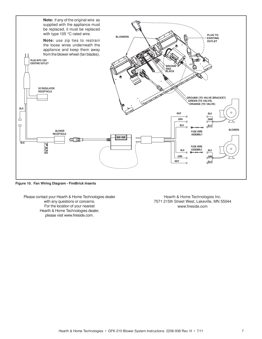
Note: if any of the original wire as supplied with the appliance must be replaced, it must be replaced with type 105 °C rated wire.
Note: use zip ties to restrain the loose wires underneath the appliance and keep them away from the blower wheel (fan blades).
PLUG INTO 120V
EXISTING OUTLET
DC REGULATOR
RECEPTACLE
BLOWER
RECEPTACLE
BLOWERS
![]() BROWN
BROWN
RED
BLACK
WHT
GRN
BLK
BLK
GRN
WHT
PLUG TO
EXISTING
OUTLET
GROUND (TO VALVE BRACKET)
GREEN (TO VALVE)
ORANGE (TO VALVE)
BLK
GRN
BLK
FUSE WIRE | BLOWERS | |
|
| |
ASSEMBLY |
|
|
|
|
|
FUSE WIRE
ASSEMBLY BLK
GRN
BLK
Figure 10. Fan Wiring Diagram - FireBrick Inserts |
|
Please contact your Hearth & Home Technologies dealer | Hearth & Home Technologies Inc. |
with any questions or concerns. | 7571 215th Street West, Lakeville, MN 55044 |
For the location of your nearest | www.fireside.com |
Hearth & Home Technologies dealer, |
|
please visit www.fireside.com. |
|
Hearth & Home Technologies • | 7 |
