E


C


A


F


V


J

B


U.S


V

V

B


B

(3 FT.)


V


i


D

V

V


G

M

X


A


V


H or i


O


V


N


P


L


R


V

K

Electrical

K

V


Service


C

Q

V

(See Note 2)

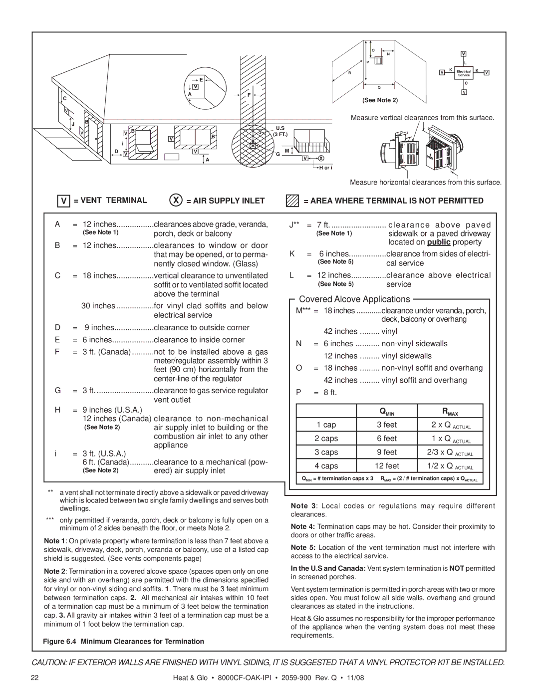
Measure vertical clearances from this surface.

Measure horizontal clearances from this surface.


V

= VENT TERMINAL

X = AIR SUPPLY INLET

A

=

12 inches

clearances above grade, veranda,


(See Note 1)

porch, deck or balcony

B

=

12 inches

clearances to window or door


that may be opened, or to perma-


nently closed window. (Glass)

C

=

18 inches

vertical clearance to unventilated


soffit or to ventilated soffit located


above the terminal


30 inches

for vinyl clad soffits and below


electrical service

D

=

9 inches

clearance to outside corner

E

=

6 inches

clearance to inside corner

F

=

3 ft. (Canada)

not to be installed above a gas


meter/regulator assembly within 3


feet (90 cm) horizontally from the


center-line of the regulator

G

=

3 ft

clearance to gas service regulator

H

=

9 inches (U.S.A.)

vent outlet


12 inches (Canada) clearance to non-mechanical


(See Note 2)

air supply inlet to building or the


combustion air inlet to any other

i

=

3 ft. (U.S.A.)

appliance


6 ft. (Canada)

clearance to a mechanical (pow-


(See Note 2)

ered) air supply inlet

**a vent shall not terminate directly above a sidewalk or paved driveway which is located between two single family dwellings and serves both dwellings.

***only permitted if veranda, porch, deck or balcony is fully open on a minimum of 2 sides beneath the floor, or meets Note 2.

Note 1: On private property where termination is less than 7 feet above a sidewalk, driveway, deck, porch, veranda or balcony, use of a listed cap shield is suggested. (See vents components page)

Note 2: Termination in a covered alcove space (spaces open only on one side and with an overhang) are permitted with the dimensions specified for vinyl or non-vinyl siding and soffits. 1. There must be 3 feet minimum between termination caps. 2. All mechanical air intakes within 10 feet of a termination cap must be a minimum of 3 feet below the termination cap. 3. All gravity air intakes within 3 feet of a termination cap must be a minimum of 1 foot below the termination cap.

Figure 6.4 Minimum Clearances for Termination

= AREA WHERE TERMINAL IS NOT PERMITTED

J**

=

7 ft

clearance above paved


(See Note 1)

sidewalk or a paved driveway


located on public property

K

=

6 inches

clearance from sides of electri-


(See Note 5)

cal service

L

=

12 inches

clearance above electrical


(See Note 5)

service

Covered Alcove Applications

M*** =

18 inches

clearance under veranda, porch,


deck, balcony or overhang


42 inches

......... vinyl


N

=

6 inches

non-vinyl sidewalls


12 inches

......... vinyl sidewalls

O

=

18 inches

......... non-vinyl soffit and overhang


42 inches

......... vinyl soffit and overhang

P

=

8 ft.


QMIN

RMAX


1 cap


3 feet

2 x Q ACTUAL


2 caps


6 feet

1 x Q ACTUAL


3 caps


9 feet

2/3 x Q ACTUAL


4 caps


12 feet

1/2 x Q ACTUAL


QMIN = # termination caps x 3 RMAX = (2 / # termination caps) x QACTUAL

Note 3: Local codes or regulations may require different clearances.

Note 4: Termination caps may be hot. Consider their proximity to doors or other traffic areas.

Note 5: Location of the vent termination must not interfere with access to the electrical service.

In the U.S and Canada: Vent system termination is NOT permitted in screened porches.

Vent system termination is permitted in porch areas with two or more sides open. You must follow all side walls, overhang and ground clearances as stated in the instructions.

Heat & Glo assumes no responsibility for the improper performance of the appliance when the venting system does not meet these requirements.

CAUTION: IF EXTERIOR WALLS ARE FINISHED WITH VINYL SIDING, IT IS SUGGESTED THAT A VINYL PROTECTOR KIT BE INSTALLED.

22

Heat & Glo • 8000CF-OAK-IPI2059-900 Rev. Q • 11/08

Page 22
Image 22
Hearth and Home Technologies 8000CF-OAK-IPI = Vent Terminal = AIR Supply Inlet, = Area Where Terminal is not Permitted

8000CF-OAK-IPI, 8000CFLP-OAKIPI specifications

Hearth and Home Technologies (HHT) is recognized for its commitment to quality and innovation in the fireplace and home heating industry. Among its popular products are the 8000CFLP-OAKIPI and 8000CF-OAK-IPI gas fireplaces, which stand out in terms of design, features, and efficiency.

The 8000CFLP-OAKIPI is a contemporary linear gas fireplace that features a stunning design suitable for modern living spaces. With its expansive viewing area, the 8000CFLP-OAKIPI provides a captivating flame presentation that transforms any room into a cozy retreat. Its clean face design eliminates a bulky frame, giving the appearance of a window to the flames. This model is equipped with LED accent lighting that enhances the ambiance further when the fireplace is not in use.

On the other hand, the 8000CF-OAK-IPI offers a more traditional design that features a classic fireplace experience while incorporating modern technology. It uses high-efficiency gas combustion to deliver unmatched warmth while ensuring minimal emissions. Both models come with the option for ceramic fiber logs, which mimic the natural look of real wood while enhancing heat production.

The advanced IntelliFire app supports both units, allowing users to control the fire conveniently via smartphone or tablet. This technology offers increased functionality, enabling users to adjust flame height, fan speed, and lighting settings for the perfect ambiance.

In terms of energy efficiency, both the 8000CFLP-OAKIPI and the 8000CF-OAK-IPI are designed to offer significant savings on heating bills. They are equipped with an electronic ignition system that offers seamless startup and optimal combustion efficiency. The design also adheres to stringent efficiency standards, ensuring that users enjoy a sustainable and cost-effective heating solution.

Installation is made straightforward with their versatile venting options, allowing for both direct vent and vent-free configurations. This flexibility ensures compatibility with various home layouts while optimizing heat distribution.

In summary, the Hearth and Home Technologies 8000CFLP-OAKIPI and 8000CF-OAK-IPI gas fireplaces represent a blend of style, technology, and efficiency. With their focus on innovation and customer satisfaction, HHT continues to lead the way in providing modern heating solutions that elevate any living space.