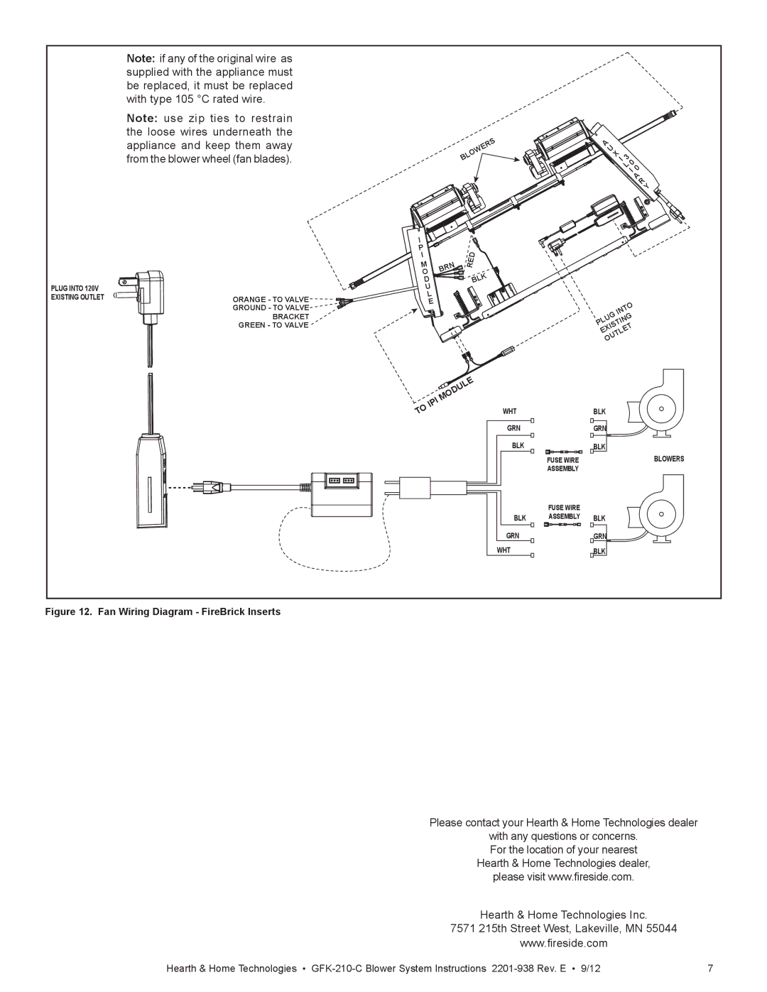
GFK-210-C specifications
Hearth and Home Technologies has introduced the GFK-210-C, a versatile and efficient heating product that combines modern technology with user-friendly features. This unit is designed to enhance the warmth of your home while providing an array of functionalities that cater to the comfort and needs of today’s homeowners.One of the standout features of the GFK-210-C is its advanced heat circulation technology. It utilizes a powerful blower system that effectively distributes warm air throughout the room, ensuring that every corner of your living space is enveloped in cozy warmth. This technology not only maximizes comfort but also improves energy efficiency, as it allows the unit to operate optimally even in larger spaces.
The GFK-210-C also features a state-of-the-art thermostat control. This intelligent system allows users to set their desired temperature, and the unit will automatically adjust its output to maintain that level of warmth consistently. This feature helps to save on energy costs while ensuring that homeowners enjoy a comfortable environment at all times.
Additionally, the GFK-210-C incorporates a sleek and modern design, making it an aesthetically pleasing option for any interior. Its compact form allows it to fit seamlessly into various settings, whether it is a traditional or contemporary home decor. The design is not just about looks; the materials used in its construction are durable and ensure a long lifespan, which is important for any heating appliance.
For added convenience, the GFK-210-C comes with a remote control. This functionality allows users to adjust settings without having to leave the comfort of their seat, showcasing the unit's commitment to user-friendly operation. This remote feature also includes programmable timer settings, providing even more control over heating schedules.
Safety is paramount, and the GFK-210-C is equipped with several safety features. This includes heat sensors and an automatic shut-off mechanism, which activate in case of overheating, providing peace of mind to users.
In summary, the Hearth and Home Technologies GFK-210-C is not just a heating appliance; it is a blend of efficiency, safety, and modern design. With its advanced heat circulation, intelligent thermostat control, convenient remote operation, and integrated safety features, it stands out as a top choice for homeowners looking to enhance their living environment.

