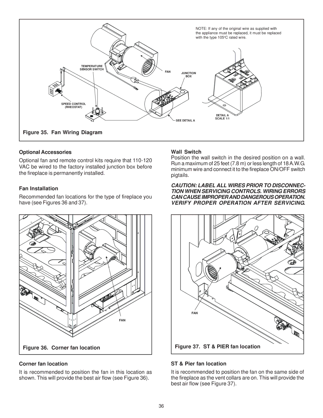
RCOR-HVB-IPI, LCOR-HVB-IPI specifications
Hearth and Home Technologies has established itself as a leading name in the hearth and home industry, providing innovative and high-performance heating solutions. Two standout products from their extensive lineup are the LCOR-HVB-IPI and RCOR-HVB-IPI. Both units exemplify the company's commitment to quality craftsmanship, modern technology, and energy efficiency.The LCOR-HVB-IPI, an attractive linear model, is designed to bring elegance and warmth to any living space. Its sleek design boasts a contemporary aesthetic, making it a perfect centerpiece for modern homes. One of the main features of the LCOR-HVB-IPI is its impressive heat output capability, ensuring that even the coldest days are comfortably warm. The unit can be controlled via a remote, allowing users to set the desired temperature with ease.
In terms of technology, the LCOR-HVB-IPI employs a sophisticated direct vent system which ensures safe and efficient combustion. This feature not only enhances the overall performance of the unit but also provides peace of mind, knowing that harmful gases are vented outside effectively. The unit is equipped with an IPI (Intermittent Pilot Ignition) system, which allows for energy savings by eliminating the need for a constantly burning pilot light.
On the other hand, the RCOR-HVB-IPI shares many of the same features but is crafted as a traditional-style fireplace. With its charming design, the RCOR-HVB-IPI integrates seamlessly into classic home decor while providing the latest in heating technology. This model also prioritizes energy efficiency, utilizing a similar direct vent system for safe operation and optimized heating.
Both models feature glass doors that provide an unobstructed view of the flames, adding to the ambience of the room. User-friendly controls make it simple to adjust settings, and the option to customize the fire media further enhances the aesthetic appeal.
Additionally, both the LCOR-HVB-IPI and RCOR-HVB-IPI are designed with environmental considerations in mind. Their high-efficiency ratings ensure that they meet or exceed industry standards for emissions, contributing to cleaner indoor air quality.
In summary, Hearth and Home Technologies’ LCOR-HVB-IPI and RCOR-HVB-IPI models are perfect examples of how modern innovation can blend with classic designs to create efficient, stylish heating solutions. Whether you're looking for a contemporary linear model or a traditional fireplace design, these units offer the best of both worlds, ensuring that your home remains warm and inviting throughout the year.