Heat Controller 
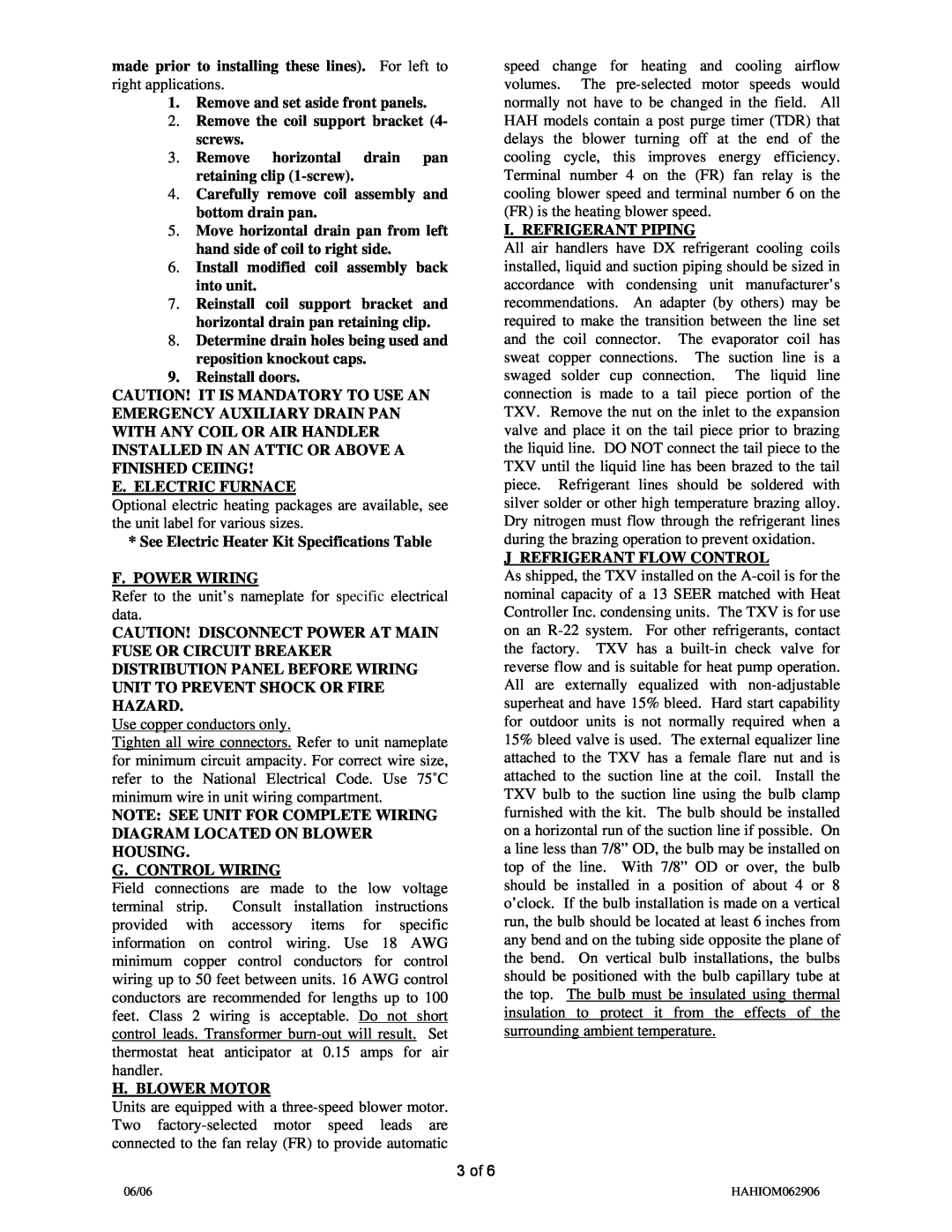
HAH13XX-00-1A Remove and set aside front panels, Reinstall doors, F. Power Wiring

Models: HAH13XX-00-1A

1 6
Download 6 pages 17.38 Kb
Page 3
Image 3

made prior to installing these lines). For left to right applications.

1.Remove and set aside front panels.

2.Remove the coil support bracket (4- screws.

3.Remove horizontal drain pan retaining clip (1-screw).

4.Carefully remove coil assembly and bottom drain pan.

5.Move horizontal drain pan from left hand side of coil to right side.

6.Install modified coil assembly back into unit.

7.Reinstall coil support bracket and horizontal drain pan retaining clip.

8.Determine drain holes being used and reposition knockout caps.

9.Reinstall doors.

CAUTION! IT IS MANDATORY TO USE AN EMERGENCY AUXILIARY DRAIN PAN WITH ANY COIL OR AIR HANDLER INSTALLED IN AN ATTIC OR ABOVE A FINISHED CEIING!

E. ELECTRIC FURNACE

Optional electric heating packages are available, see the unit label for various sizes.

*See Electric Heater Kit Specifications Table

F. POWER WIRING

Refer to the unit’s nameplate for specific electrical data.

CAUTION! DISCONNECT POWER AT MAIN FUSE OR CIRCUIT BREAKER DISTRIBUTION PANEL BEFORE WIRING UNIT TO PREVENT SHOCK OR FIRE HAZARD.

Use copper conductors only.

Tighten all wire connectors. Refer to unit nameplate for minimum circuit ampacity. For correct wire size, refer to the National Electrical Code. Use 75˚C minimum wire in unit wiring compartment.

NOTE: SEE UNIT FOR COMPLETE WIRING DIAGRAM LOCATED ON BLOWER HOUSING.

G. CONTROL WIRING

Field connections are made to the low voltage terminal strip. Consult installation instructions provided with accessory items for specific information on control wiring. Use 18 AWG minimum copper control conductors for control wiring up to 50 feet between units. 16 AWG control conductors are recommended for lengths up to 100 feet. Class 2 wiring is acceptable. Do not short control leads. Transformer burn-out will result. Set thermostat heat anticipator at 0.15 amps for air handler.

H. BLOWER MOTOR

Units are equipped with a three-speed blower motor. Two factory-selected motor speed leads are connected to the fan relay (FR) to provide automatic

3 of 6

speed change for heating and cooling airflow volumes. The pre-selected motor speeds would normally not have to be changed in the field. All HAH models contain a post purge timer (TDR) that delays the blower turning off at the end of the cooling cycle, this improves energy efficiency. Terminal number 4 on the (FR) fan relay is the cooling blower speed and terminal number 6 on the (FR) is the heating blower speed.

I. REFRIGERANT PIPING

All air handlers have DX refrigerant cooling coils installed, liquid and suction piping should be sized in accordance with condensing unit manufacturer’s recommendations. An adapter (by others) may be required to make the transition between the line set and the coil connector. The evaporator coil has sweat copper connections. The suction line is a swaged solder cup connection. The liquid line connection is made to a tail piece portion of the TXV. Remove the nut on the inlet to the expansion valve and place it on the tail piece prior to brazing the liquid line. DO NOT connect the tail piece to the TXV until the liquid line has been brazed to the tail piece. Refrigerant lines should be soldered with silver solder or other high temperature brazing alloy. Dry nitrogen must flow through the refrigerant lines during the brazing operation to prevent oxidation.

J REFRIGERANT FLOW CONTROL

As shipped, the TXV installed on the A-coil is for the nominal capacity of a 13 SEER matched with Heat Controller Inc. condensing units. The TXV is for use on an R-22 system. For other refrigerants, contact the factory. TXV has a built-in check valve for reverse flow and is suitable for heat pump operation. All are externally equalized with non-adjustable superheat and have 15% bleed. Hard start capability for outdoor units is not normally required when a 15% bleed valve is used. The external equalizer line attached to the TXV has a female flare nut and is attached to the suction line at the coil. Install the TXV bulb to the suction line using the bulb clamp furnished with the kit. The bulb should be installed on a horizontal run of the suction line if possible. On a line less than 7/8” OD, the bulb may be installed on top of the line. With 7/8” OD or over, the bulb should be installed in a position of about 4 or 8 o’clock. If the bulb installation is made on a vertical run, the bulb should be located at least 6 inches from any bend and on the tubing side opposite the plane of the bend. On vertical bulb installations, the bulbs should be positioned with the bulb capillary tube at the top. The bulb must be insulated using thermal insulation to protect it from the effects of the surrounding ambient temperature.

06/06

HAHIOM062906

Page 3
Image 3
Heat Controller HAH13XX-00-1A manual Remove and set aside front panels, Remove the coil support bracket 4- screws