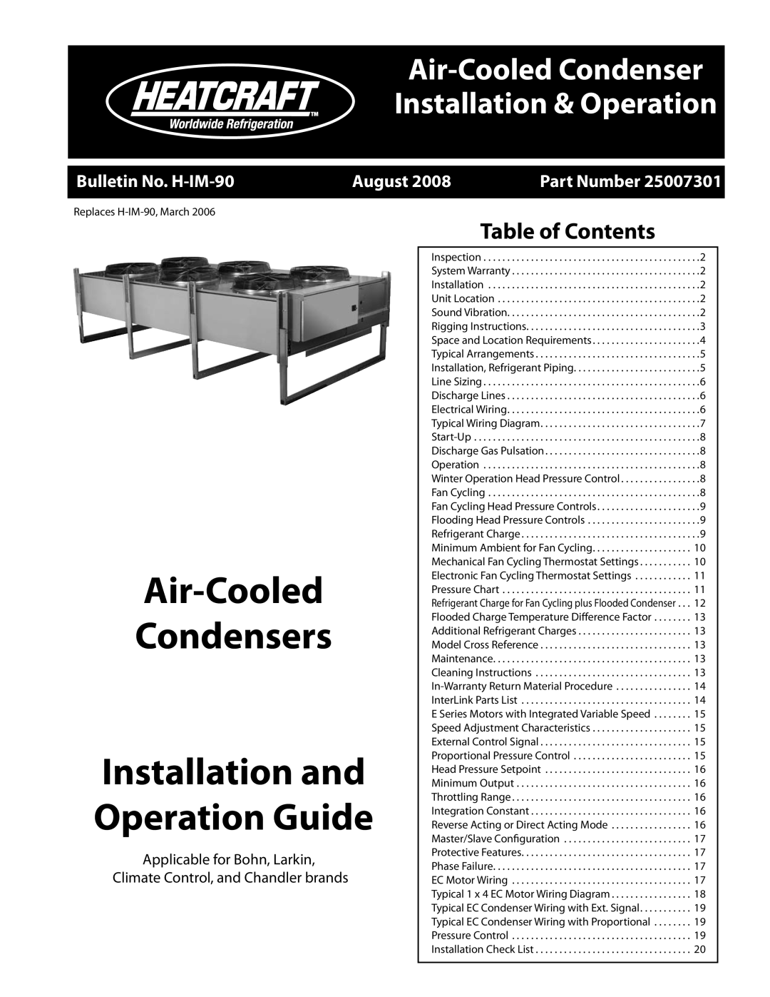
none specifications
Heatcraft Refrigeration Products is a recognized leader in providing innovative and energy-efficient cooling solutions. The company specializes in manufacturing an extensive array of refrigeration systems designed to meet the demands of various commercial applications. With a strong commitment to quality and sustainability, Heatcraft integrates advanced engineering principles in every product, ensuring reliability and performance.One of the standout features of Heatcraft products is their versatility. The company offers a wide range of refrigeration units, including condensing units, evaporators, and packaged systems, designed to accommodate different operational requirements. Whether it's for supermarkets, restaurants, or cold storage facilities, Heatcraft provides solutions that ensure optimal temperature control and energy efficiency.
Heatcraft places a significant emphasis on energy efficiency, developing technologies that help reduce operational costs while minimizing the environmental impact. Their products often incorporate advanced compressor systems, environmentally friendly refrigerants, and intelligent controls that adjust performance based on real-time conditions. This focus on energy-saving innovations not only benefits the planet but also boosts the bottom line for businesses that rely on refrigeration.
Furthermore, Heatcraft is known for its user-friendly design and ease of installation. Their systems are engineered for straightforward setup and maintenance, allowing businesses to minimize downtime and ensure seamless operations. This design philosophy extends to the company’s extensive catalog of components and accessories, providing customers with a comprehensive suite of options tailored to their specific needs.
Heatcraft also prioritizes customer support and service, offering resources and training for technicians to enhance their expertise in handling refrigeration systems. With a strong distribution network and support from knowledgeable representatives, customers can be assured that help is always accessible.
In addition, Heatcraft values innovation and continuously invests in research and development to stay ahead of industry trends. This dedication to advancement ensures that their products not only conform to current regulations but also anticipate future needs in the refrigeration sector.
Overall, Heatcraft Refrigeration Products exemplifies excellence in design, efficiency, and support, establishing itself as a trusted partner in the HVAC and refrigeration industries. Their commitment to quality and sustainability positions them as a frontrunner, meeting the evolving demands of a diverse market.

