
SL-4300 specifications
The Heath Zenith SL-4300 is a sophisticated and versatile motion-activated outdoor security light designed to enhance home safety while providing a range of convenient features. With an emphasis on reliability and functionality, the SL-4300 boasts several technologies that make it a preferred choice for homeowners seeking to enhance their outdoor lighting systems.One of the standout features of the SL-4300 is its dual-head design, which allows for adjustable positioning of the light heads to illuminate various areas effectively. Each head can be pointed in different directions, ensuring maximum coverage of your outdoor spaces. This adaptability is crucial for monitoring large areas, such as driveways, patios, and gardens.
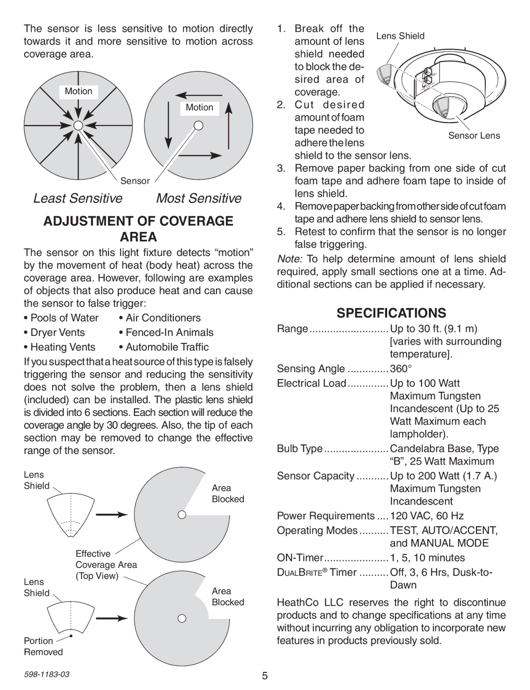
The motion detection technology employed by the SL-4300 is advanced and precise. It utilizes passive infrared (PIR) sensors to detect movement within a 180-degree field of view, offering a range of up to 30 feet. This ensures that any motion detected triggers the light, providing bright illumination to deter unwanted visitors and enhance safety during nighttime hours.
In terms of luminosity, the SL-4300 features energy-efficient LED bulbs that deliver substantial brightness while consuming minimal energy. The LED lights not only have a long lifespan, reducing the need for frequent bulb replacements, but they also lower electricity costs compared to traditional incandescent bulbs. With a luminous output that effectively lights up the space without harsh glare, the SL-4300 maintains a welcoming and secure atmosphere around the home.
Installation of the SL-4300 is simple, thanks to its user-friendly design. It comes with all the necessary mounting hardware and a clear instruction manual, making it accessible even for those with basic DIY skills. The unit is constructed from durable materials that can withstand varying weather conditions, ensuring longevity and consistent performance.
Another key feature of the SL-4300 is the adjustable timer and sensitivity settings. Users can customize the duration the light stays on after activation, ranging from a few seconds to several minutes. Additionally, sensitivity settings allow users to determine the threshold for triggering the light, which is particularly useful in reducing false alarms caused by animals or passersby.
In summary, the Heath Zenith SL-4300 is a state-of-the-art motion-activated outdoor security light that combines practical design elements, innovative technologies, and user-friendly features. With its superior motion detection system, energy-efficient LED lighting, adjustable settings, and durable construction, it stands as a robust solution for enhancing outdoor safety and security for any home.