Drive Housing
Removal
1.
Relieve pressure; page 6.
2.Disconnect reed switch (A).
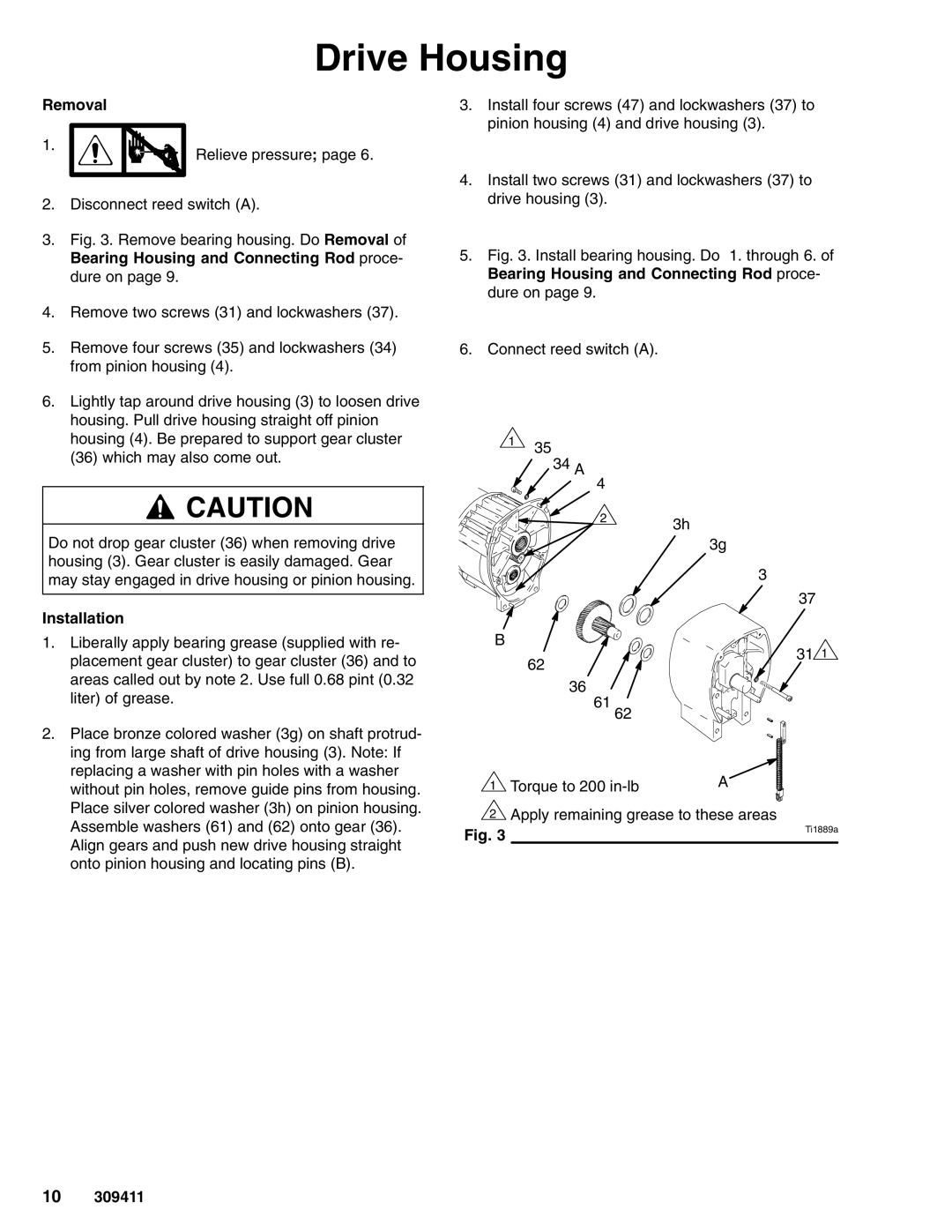
3.Fig. 3. Remove bearing housing. Do Removal of Bearing Housing and Connecting Rod proce- dure on page 9.
4.Remove two screws (31) and lockwashers (37).
5.Remove four screws (35) and lockwashers (34) from pinion housing (4).
6.Lightly tap around drive housing (3) to loosen drive housing. Pull drive housing straight off pinion housing (4). Be prepared to support gear cluster (36) which may also come out.
![]() CAUTION
CAUTION
Do not drop gear cluster (36) when removing drive housing (3). Gear cluster is easily damaged. Gear may stay engaged in drive housing or pinion housing.
3.Install four screws (47) and lockwashers (37) to pinion housing (4) and drive housing (3).
4.Install two screws (31) and lockwashers (37) to drive housing (3).
5.Fig. 3. Install bearing housing. Do 1. through 6. of Bearing Housing and Connecting Rod proce- dure on page 9.
6.Connect reed switch (A).
135
34 A  4
4
23h
3g
3
Installation
1. Liberally apply bearing grease (supplied with re- |
placement gear cluster) to gear cluster (36) and to |
areas called out by note 2. Use full 0.68 pint (0.32 |
B
62
37
31 1
liter) of grease. |
2. Place bronze colored washer (3g) on shaft protrud- |
ing from large shaft of drive housing (3). Note: If |
replacing a washer with pin holes with a washer |
without pin holes, remove guide pins from housing. |
Place silver colored washer (3h) on pinion housing. |
Assemble washers (61) and (62) onto gear (36). |
Align gears and push new drive housing straight |
onto pinion housing and locating pins (B). |
36
61
62
1 Torque to 200 | A |
|
2Apply remaining grease to these areas
Fig. 3 | Ti1889a |
|
10309411
