SAW MOUNTED TO WORK SURFACE (Fig. B)
1.If the leg set will not be used, the saw must be properly secured to a sturdy workbench using the four mounting holes at the base of the saw.
2.The surface of the table where the saw is to be mounted must have a hole large enough to facilitate sawdust
3.Square the saw on the mounting surface and mark the location of the four 3/8" mounting holes (1).
4.Drill 3/8" hole into the mounting surface.
5.Mark an 11" square (2) centered between the four mounting holes (1).
6.Cut out and remove the square.
7.This opening will allow sawdust to fall through the saw base.
8.Place the saw on the work surface, and align the mounting holes of the saw with those drilled through the surface.
9.Fasten the saw to the work surface.
![]() WARNING
WARNING
Do not operate this machine on the floor. This is very dangerous and may cause serious injury.
Fig. B
S QU AR E
CU T OU T2
1
![]() WARNING
WARNING
Failure to provide the sawdust
KEEPING THE AREA CLEAN
1.Sawdust and wood chips that fall from under the saw will accumulate on the floor.
2.Make it a practice to pick up and discard this dust when you have completed cutting.
ADJUSTING THE CUTTING LINE INDICATOR (Fig. C)
1.Take off the cover (1)by loosening screws (2).
2.Adjust the pointer (3) to align to the blade.
3.Mount the cover on the table to fix the pointer. NOTE: The pointer was set up to align to the right side of the blade when packing.
Fig. C
3 | 1 |
| |
| 2 |
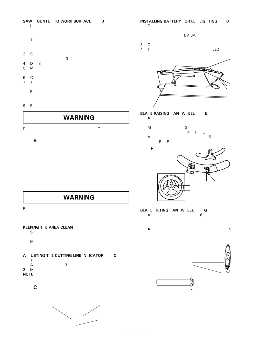
INSTALLING BATTERY FOR LED LIGHTING(Fig. B)
1.Open the cover (1) of battery box on the top of blade guard.
2.Install 2 pieces of 1.5V 3A batteries into the battery box in right direction.
3.Close the cover.
4.Turn on the switch (2) to check the LED lighting.
Fig. D | 2 |
|
1
BLADE RAISING HANDWHEEL (Fig. E, F)
1.Attach the handwheel (1) to the elevation screw (2) at the front of the saw.
Make sure the slots (3) in the hub of the handwheel engage with the pins (4). (Fig. E)
2.Attach and tighten the dome nut (5) at the end of the shaft (Fig. F).
Fig. E
3 | 2 | 4 |
|
| |
1 |
|
|
BLADE TILTING HANDWHEEL (Fig. G, F)
1.Attach the other handwheel (6) to the blade tilting screw on the side of the saw in the same manner as above.
2.Attach and tighten the handwheel dome nut (5).
Fig. F
5
6
— 11 —