English
Saw Blade
DownLoosen
Up
Tighten Tilt Lock
Handle
Wheel
rIf the saw blade is not at a left bevel 45°, loosen the saw blade tilt lock handle. Loosen the 6mm machine screw (B) (see Fig.
tAfter adjustment, tighten the saw blade tilt lock handle.
yOn completion of adjustment, recheck the left 45° bevel of the saw blade and table.
Fig.
Saw Blade
45° Gauge
Fig.
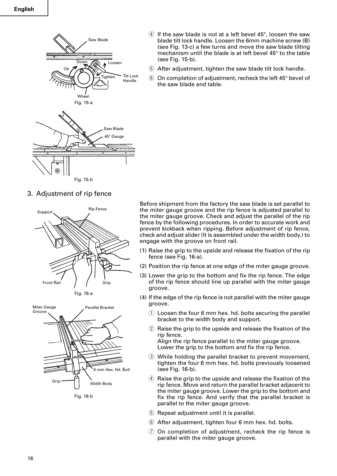
3. Adjustment of rip fence
Rip Fence
Support
Front Rail | Grip |
| Fig. |
Miter Gauge | Parallel Bracket |
Groove |
|
Before shipment from the factory the saw blade is set parallel to the miter gauge groove and the rip fence is adjusted parallel to the miter gauge groove. Check and adjust the parallel of the rip fence by the following procedures. In order to accurate work and prevent kickback when ripping. Before adjustment of rip fence, check and adjust slider (It is assembled under the width body.) to engage with the groove on front rail.
(1) | Raise the grip to the upside and release the fixation of the rip |
| fence (see Fig. |
(2) | Position the rip fence at one edge of the miter gauge groove. |
(3) | Lower the grip to the bottom and fix the rip fence. The edge |
| of the rip fence should line up parallel with the miter gauge |
| groove. |
(4) | If the edge of the rip fence is not parallel with the miter gauge |
| groove. |
| q Loosen the four 6 mm hex. hd. bolts securing the parallel |
| bracket to the width body and support. |
| w Raise the grip to the upside and release the fixation of the |
| rip fence. |
| Align the rip fence parallel to the miter gauge groove. |
| Lower the grip to the bottom and fix the rip fence. |
| e While holding the parallel bracket to prevent movement, |
| tighten the four 6 mm hex. hd. bolts previously loosened |
Grip
6 mm Hex. Hd. Bolt
Width Body
(see Fig. |
r Raise the grip to the upside and release the fixation of the |
rip fence. Move and return the parallel bracket adjacent to |
the miter gauge groove. Lower the grip to the bottom and |
Fig.
fix the rip fence. And verify that the parallel bracket is |
parallel to the miter gauge groove. |
t Repeat adjustment until it is parallel. |
y After adjustment, tighten four 6 mm hex. hd. bolts. |
u On completion of adjustment, recheck the rip fence is |
parallel with the miter gauge groove. |
16