CHAPTER 2
D I S A S S E M B L Y
1. Before Starting Disassembly
1)Unplug the power cord from the AC outlet.
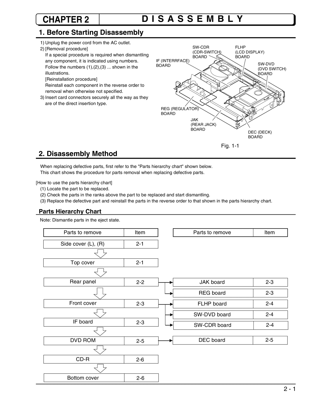
2)[Removal procedure]
If a special procedure is required when dismantling any component, it is indicated using numbers. Follow the numbers (1),(2),(3) ... shown in the illustrations.
[Reinstallation procedure]
Reinstall each component in the reverse order to removal when otherwise not specified.
3)Insert card connectors securely all the way as they are of the direct insertion type.
2. Disassembly Method
FLHP | |
(LCD DISPLAY) | |
BOARD | BOARD |
IF (INTERRFACE)
BOARD | ||
(DVD SWITCH) | ||
| ||
| BOARD |
REG (REGULATOR)
BOARD
JAK
(REAR JACK)
BOARD
DEC (DECK)
BOARD
Fig.
When replacing defective parts, first refer to the "Parts hierarchy chart" shown below.
This chart shows the procedure for parts removal when replacing defective parts.
[How to use the parts hierarchy chart]
(1)Locate the part to be replaced.
(2)Check the parts in the ranks above the part to be replaced and start dismantling.
(3)Replace the defective part and reinstall the parts in the reverse order to that shown in the parts hierarchy chart.
Parts Hierarchy Chart
Note: Dismantle parts in the eject state.
Parts to remove | Item |
|
| ||
|
|
|
|
|
|
|
|
|
|
|
|
Side cover (L), (R) |
|
| |||
|
|
|
|
|
|
|
|
|
|
|
|
Top cover |
|
| |||
|
|
|
|
|
|
|
|
|
|
|
|
Rear panel |
|
| |||
|
| ||||
|
|
|
|
|
|
|
|
|
|
|
|
|
|
|
|
|
|
|
|
|
| ||
Front cover |
|
| |||
|
| ||||
|
|
|
|
|
|
|
|
|
|
|
|
|
|
|
|
|
|
IF board |
|
| |||
|
|
|
|
|
|
Parts to remove | Item |
|
|
JAK board |
| |
REG board |
| |
| ||
FLHP board |
|
|
| ||
| ||
| ||
| ||
| ||
|
|
|
|
|
|
| ||
|
|
|
DVD ROM
DEC board
| Bottom cover |
| |
|
|
|
|
|
|
|
|
2 - 1