6-4. Changing Drive Roll Or Wire Inlet Guide
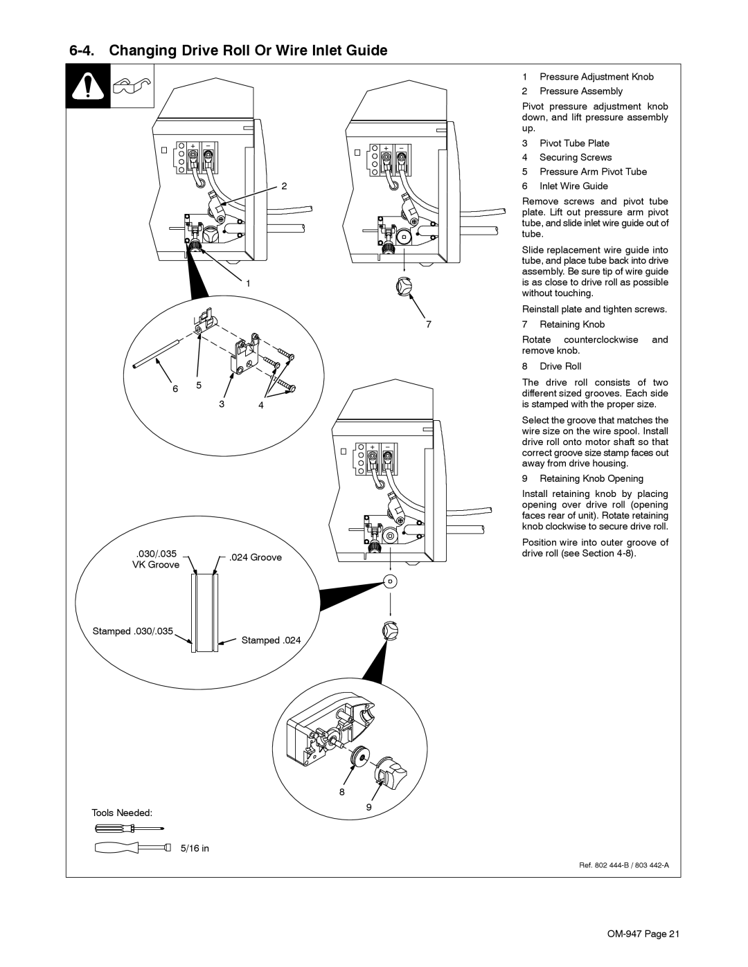
| 1 | Pressure Adjustment Knob |
| 2 | Pressure Assembly |
| Pivot pressure adjustment knob | |
| down, and lift pressure assembly | |
| up. |
|
| 3 | Pivot Tube Plate |
| 4 | Securing Screws |
| 5 | Pressure Arm Pivot Tube |
2 | 6 | Inlet Wire Guide |
| Remove screws and pivot tube | |
| plate. Lift out pressure arm pivot | |
| tube, and slide inlet wire guide out of | |
| tube. | |
| Slide replacement wire guide into | |
| tube, and place tube back into drive | |
| assembly. Be sure tip of wire guide | |
1 | is as close to drive roll as possible | |
| without touching. | |
| Reinstall plate and tighten screws. | |
6 5
.030/.035 VK Groove
3 4
.024 Groove
7 | 7 | Retaining Knob |
| Rotate counterclockwise and | |
| remove knob. | |
| 8 | Drive Roll |
| The drive roll consists of two | |
| different sized grooves. Each side | |
| is stamped with the proper size. | |
| Select the groove that matches the | |
| wire size on the wire spool. Install | |
| drive roll onto motor shaft so that | |
| correct groove size stamp faces out | |
| away from drive housing. | |
| 9 | Retaining Knob Opening |
| Install retaining knob by placing | |
| opening over drive roll (opening | |
| faces rear of unit). Rotate retaining | |
| knob clockwise to secure drive roll. | |
Position wire into outer groove of drive roll (see Section
Stamped .030/.035
Tools Needed:
5/16 in
Stamped .024
8![]()
9
Ref. 802