ASSEMBLY INSTRUCTIONS:
Carefully unpack contents of carton.
Base Assembly:
You will need the base cover, weighted insert, 1 pole (either can be used, they are interchangeable) and base nut.
STEP 1. Insert 1 pole through the base cover and twist pole clockwise to
lock in position. |
|
|
|
|
|
|
|
|
|
|
|
Be careful to |
| (fig 1) |
|
|
|
|
|
|
| POLE | |
align the |
|
|
|
|
|
|
|
|
| THREADED JOINT | |
|
|
| |||||||||
cutaway / |
|
|
|
|
|
|
|
|
| (male end) | |
grooves on the |
|
|
|
|
|
|
|
|
| HOLLOW END OF | |
threaded joint | CUTAWAY/ |
|
|
|
|
|
| ||||
|
|
|
|
|
| BASE COVER | |||||
(male end), |
|
|
|
|
|
|
|
|
| ON TOP | |
GROOVES |
|
|
|
|
|
| |||||
(see figure # 1) |
| ▼ | |||||||||
with the two |
|
|
|
|
|
|
|
|
|
| BASE COVER |
|
|
|
|
|
|
|
|
|
| ||
protruding |
|
|
|
|
|
|
|
|
|
| WEIGHTED INSERT |
|
|
|
|
|
|
|
|
|
| ||
raised pieces |
|
|
|
|
|
|
|
|
| BASE NUT | |
inside the hol- |
|
|
|
|
|
|
|
|
| ||
|
|
|
|
|
|
|
|
| |||
low end of the |
|
|
|
|
|
|
|
|
|
|
|
base cover, |
|
|
|
|
|
|
|
|
|
|
|
|
|
|
|
|
|
|
|
|
|
| |
(see figure #1). |
|
|
|
|
|
|
|
|
|
|
|
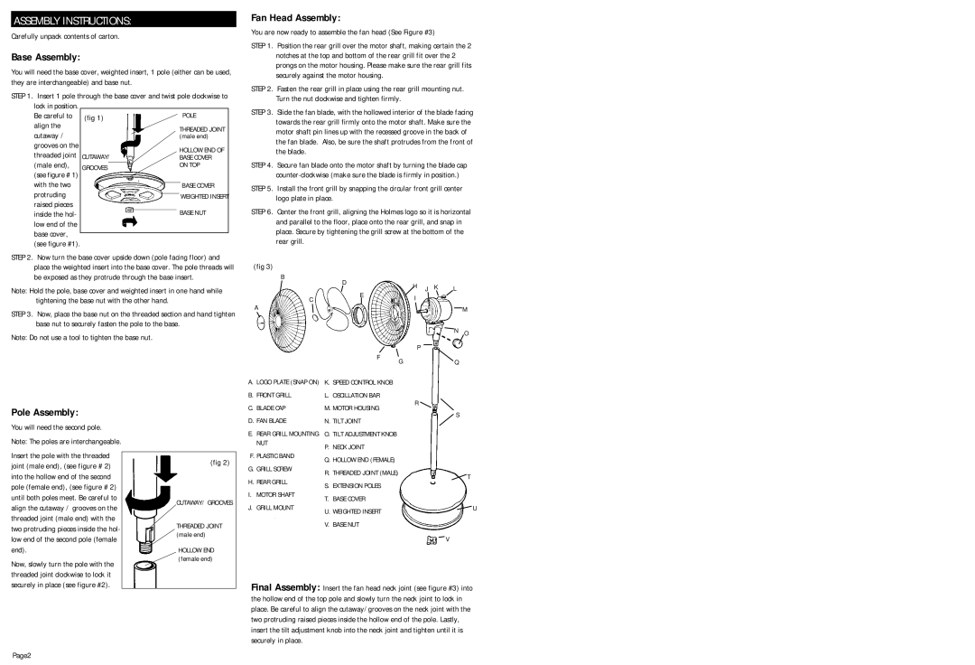
Fan Head Assembly:
You are now ready to assemble the fan head (See Figure #3)
STEP 1. Position the rear grill over the motor shaft, making certain the 2 notches at the top and bottom of the rear grill fit over the 2 prongs on the motor housing. Please make sure the rear grill fits securely against the motor housing.
STEP 2. Fasten the rear grill in place using the rear grill mounting nut. Turn the nut clockwise and tighten firmly.
STEP 3. Slide the fan blade, with the hollowed interior of the blade facing towards the rear grill firmly onto the motor shaft. Make sure the motor shaft pin lines up with the recessed groove in the back of the fan blade. Also, be sure the shaft protrudes from the front of the blade.
STEP 4. Secure fan blade onto the motor shaft by turning the blade cap
STEP 5. Install the front grill by snapping the circular front grill center logo plate in place.
STEP 6. Center the front grill, aligning the Holmes logo so it is horizontal and parallel to the floor, place onto the rear grill, and snap in place. Secure by tightening the grill screw at the bottom of the rear grill.
STEP 2. Now turn the base cover upside down (pole facing floor) and place the weighted insert into the base cover. The pole threads will be exposed as they protrude through the base insert.
Note: Hold the pole, base cover and weighted insert in one hand while tightening the base nut with the other hand.
STEP 3. Now, place the base nut on the threaded section and hand tighten base nut to securely fasten the pole to the base.
Note: Do not use a tool to tighten the base nut.
(fig 3)
B
D
C![]() E
E
A
F G
H J K | L |
I |
|
| M |
| N O |
P |
|
| Q |
Pole Assembly:
You will need the second pole. Note: The poles are interchangeable.
Insert the pole with the threaded joint (male end), (see figure # 2) into the hollow end of the second pole (female end), (see figure # 2) until both poles meet. Be careful to align the cutaway / grooves on the threaded joint (male end) with the two protruding pieces inside the hol- low end of the second pole (female end).
Now, slowly turn the pole with the threaded joint clockwise to lock it
(fig 2)
CUTAWAY/ GROOVES
THREADED JOINT (male end)
HOLLOW END (female end)
A.LOGO PLATE (SNAP ON)
B.FRONT GRILL
C.BLADE CAP
D.FAN BLADE
E.REAR GRILL MOUNTING NUT
F.PLASTIC BAND
G.GRILL SCREW
H.REAR GRILL
I.MOTOR SHAFT
J.GRILL MOUNT
K.SPEED CONTROL KNOB
L.OSCILLATION BAR
M.MOTOR HOUSING
N.TILT JOINT
O.TILT ADJUSTMENT KNOB
P.NECK JOINT
Q.HOLLOW END (FEMALE)
R.THREADED JOINT (MALE)
S.EXTENSION POLES
T.BASE COVER
U.WEIGHTED INSERT
V.BASE NUT
R |
S |
T
U
V
securely in place (see figure #2).
Page2
Final Assembly: Insert the fan head neck joint (see figure #3) into the hollow end of the top pole and slowly turn the neck joint to lock in place. Be careful to align the cutaway/grooves on the neck joint with the two protruding raised pieces inside the hollow end of the pole. Lastly, insert the tilt adjustment knob into the neck joint and tighten until it is securely in place.